Magnetostrictive electrical switching device

A technology for electric switches and switch mechanisms, applied in magnetostrictive relays, protective switches, emergency protection devices, etc., can solve problems such as unsuitable, electromagnetic release devices not suitable for leakage circuit breakers, etc.

Inactive Publication Date: 2009-03-18
ABB (SCHWEIZ) AG
View PDF2 Cites 3 Cited by
  • Summary
  • Abstract
  • Description
  • Claims
  • Application Information

AI Technical Summary

Problems solved by technology

However, release devices for earth leakage circuit breakers are neither suitable for contactors nor circuit breakers; on the contrary, electromagnetic release devices that can be accommodated in circuit breakers are not suitable, at least if the release device is used to act independently of the system voltage Suitable for leakage circuit breakers

Method used


Image

  • Magnetostrictive electrical switching device
  • Magnetostrictive electrical switching device
  • Magnetostrictive electrical switching device

Examples


Embodiment Construction

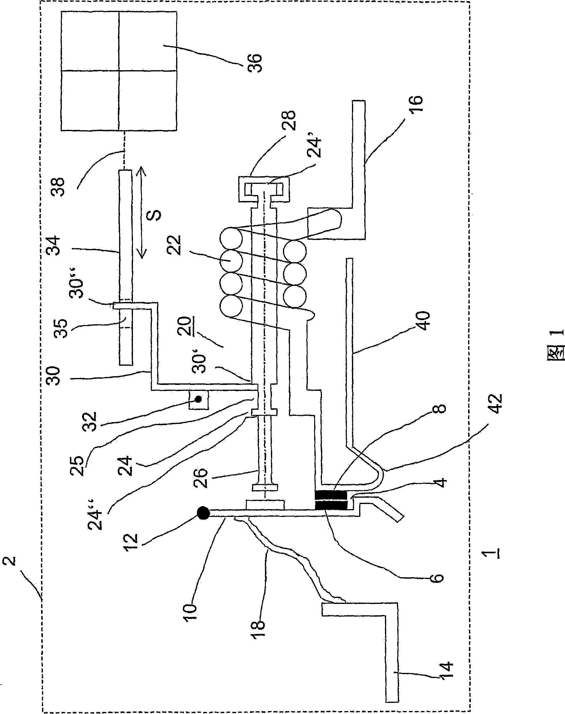
[0025] Refer to Figure 1.

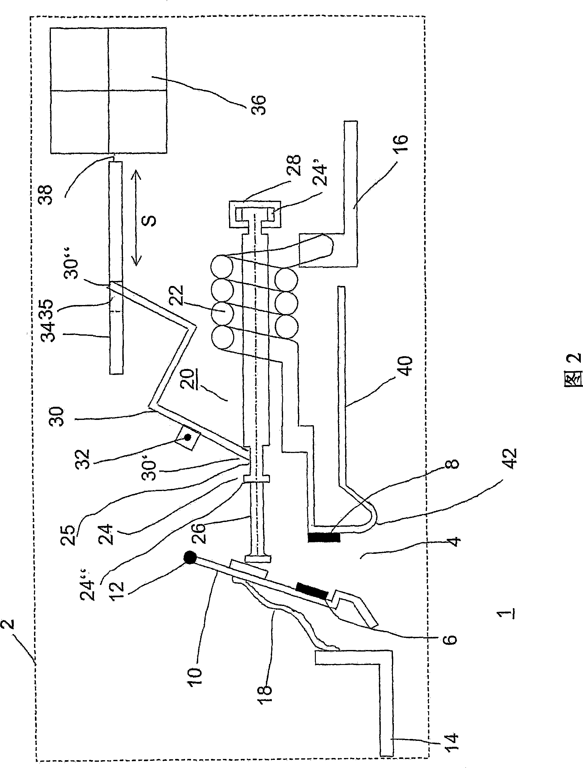
[0026] FIG. 1 schematically shows a switching device 1 in a non-tripped state with a housing 2 , an electromagnetic release device 20 and a switching mechanism 36 . FIG. 2 shows the switching device shown in FIG. 1 in a tripped state, wherein identical or similar functional assemblies or components are indicated by the same reference numerals. The current path is through the movable litz wire 18, the contact rod 10 installed in the contact rod holder 12, the contact point 4 including the movable contact 6 and the fixed contact 8 on the contact rod 10, and the trip coil 22 at the input clamping. Extends between member 14 and output clamping member 16 . In the switching position shown in FIG. 1, the contact point 4 is closed. The yoke 40 is also connected to the trip coil 22 and the stationary contact 8 via a lug-shaped intermediate piece 42 .

[0027] A thermally sensitive release, not shown, is additionally included in some switching devices and ...


PUM


Abstract

The invention proposes an electrical switching device having at least one contact point having at least one drive, which opens the contact point directly and / or via a switching mechanism with a latching point and which drive has an element having a predetermined shape, which element consists of a shape memory alloy, which changes its shape under the influence of an electromagnetic field and, in the process, opens or closes a contact point or double contact point or unlatches a switching mechanism.

Description

technical field [0001] The invention relates to an electrical switching device with at least one contact point, which is opened directly by means of an actuator or via a switching mechanism with a latching point, wherein the actuator opens the latching point and / or the contact point . Background technique [0002] Electrical switching devices in this sense are line circuit breakers, earth leakage circuit breakers, power circuit breakers, etc., as well as contactors. [0003] In the case of circuit breakers, a switching mechanism is provided with a latching point which is unlocked on the one hand by means of a thermally sensitive release (e.g. by a bimetallic or shape memory alloy strip) to open the contacts; on the other hand On the other hand, the thermal release trips if an overcurrent occurs. Because the circuit breaker also needs to open the short circuit, an electromagnetic release device with a coil, yoke, core and armature is also provided; A connection in the form...

Claims


Application Information

Patent Timeline
Patent Type & Authority Applications(China)
IPC IPC(8): H01H55/00H01H71/12
CPCH01H71/127C08L2201/12H01H71/145H01H2300/034H01H55/00
Inventor 帕特里克·克莱伊斯约阿希姆·贝克尔拉尔夫·韦伯里夏德·科默特
Owner ABB (SCHWEIZ) AG
Why Eureka
Try Eureka