Damper for furniture

A buffer and furniture technology, applied in the field of folding buffers, can solve the problems of unfavorable buffer strength, high material stress, loss, etc.

Active Publication Date: 2009-03-25
HETTICH ONI
View PDF2 Cites 8 Cited by
  • Summary
  • Abstract
  • Description
  • Claims
  • Application Information

AI Technical Summary

Problems solved by technology

Although it is thus possible to achieve a different damping force when the piston moves in the opposite direction, the strength of the da

Method used


Image

  • Damper for furniture
  • Damper for furniture
  • Damper for furniture

Examples


Embodiment Construction

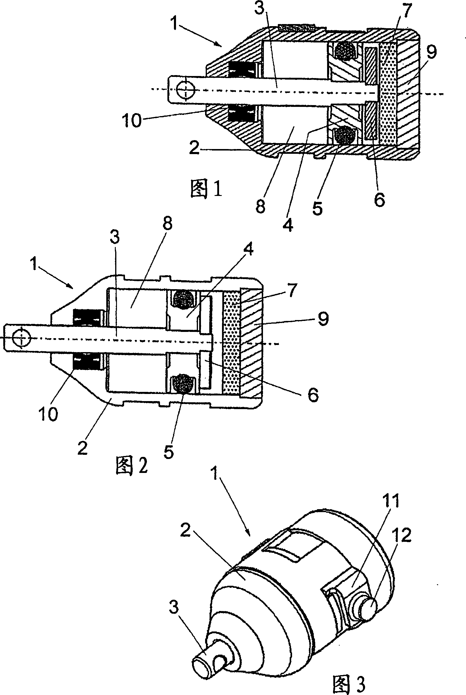
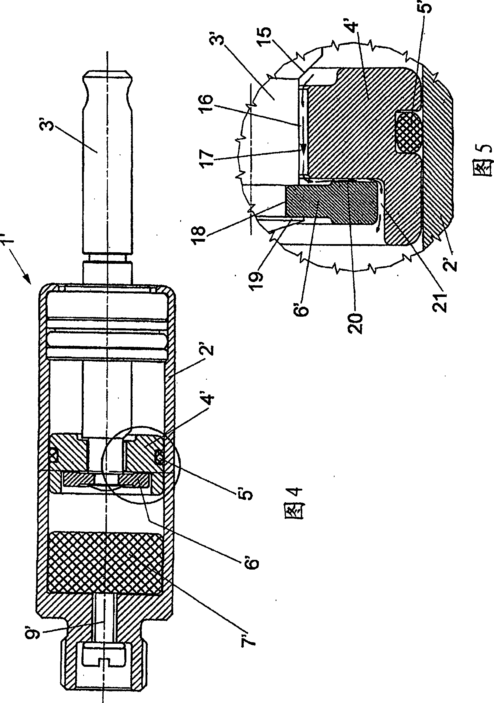
[0031] A pull-out damper 1 comprises a housing 2 and a cylindrical interior, in which a piston 4 is displaceably guided and held on a piston rod 3 . A sealing ring 5 , which bears against the inner wall of the housing 2 , is held in a groove on the outer circumference of the piston 4 .

[0032] A plate 6 is secured to one end of the piston rod 3 adjacent to the piston 4 . The above-mentioned piston 4 can move slightly axially on the piston rod 3 so that the distance between the plate 6 and the piston 4 can be changed.

[0033] An elastic foam material 7 is arranged adjacent to the plate 6 on the pressure-free side of the housing 2 and ensures a certain volume compensation when the piston rod 3 is drawn in and out of the housing. A fluid-filled interior 8 is provided on the opposite side of the piston 4 . Furthermore, the housing 2 is closed by a housing cover 9 . On the side opposite the cover 9 , the piston rod 3 is led out of the housing 2 in a sealing-tight manner via a ...


PUM


Abstract

The invention relates to a damper (1) for furniture, especially for hinges, comprising a housing (2) in which a piston (4) connected to a piston rod (3) is received in a mobile manner. When the piston (4) is displaced, a fluid flows inside the housing (2) through a flow channel (20) arranged on or in the piston (4), a different damping force being generated when the piston (4) is displaced in different directions. Parts of the cross-section of the flow channel (20) can be modified by displacing the piston (4) in relation to a plate (6), the plate (6) and/or the piston (4) comprising radially extending grooves forming at least part of the flow channel (20).

Description

technical field [0001] The invention relates to a damper for furniture, in particular for hinges, having a housing in which a piston connected to a piston rod is movably accommodated, wherein a fluid passes through the housing during movement of the piston A flow channel flows on or in the piston, wherein different damping forces result when the piston moves in different directions. Background technique [0002] There is a damper for furniture in which a microscopic hole is provided in the piston so that as the piston moves, a fluid can flow from one side of the piston to the other so that the movement of the piston passes through the Fluid is buffered. When producing such micro-holes, most of which are smaller than 0.15 mm, the disadvantage arises that the production process is time-consuming, since high precision is required and, moreover, the tool is subject to high wear and tear. Small dimensional deviations can make all the difference in cushioning power. Furthermore...

Claims


Application Information

Patent Timeline
IPC IPC(8): E05F5/10F16F9/00F16F9/516
CPCE05F5/006F16F9/003E05Y2201/21E05Y2600/53E05F5/10E05Y2900/20F16F9/516E05Y2201/256E05Y2201/264E05F5/02F16F9/00
Inventor C·罗梅尔曼W·贝克曼
Owner HETTICH ONI
Why Eureka
Try Eureka