Non-contacting intelligent electric throttle

An electronic throttle and non-contact technology, which is applied in the direction of instruments, computer control, simulators, etc., can solve the problems of poor environmental adaptability, wear of resistors, and low service life, and achieve multi-functional and intelligent functions , high reliability, and the effect of increasing drivability

Inactive Publication Date: 2009-04-22
SICHUAN HONGGUANG AUTO MACHINERY ELECTRONICS
View PDF0 Cites 8 Cited by
  • Summary
  • Abstract
  • Description
  • Claims
  • Application Information

AI Technical Summary

Problems solved by technology

The mechanical throttle is mainly used for the mechanical throttle. The main problem is that it is connected by a steel wire, which is easy to wear and the control is not accurate. Now the engine control system is gradually replacing it with an electronic throttle.
[0003] At present, most electronic throttles use contact angle sensors, the principle of which is the same as that of slide wire rheostats. The resistor body is worn during use, so the service life is not high. In extreme environments such as temperature and humidity, there are problems of poor environmental adaptability, and there is also the problem of single function

Method used


Image

  • Non-contacting intelligent electric throttle
  • Non-contacting intelligent electric throttle
  • Non-contacting intelligent electric throttle

Examples


Embodiment Construction

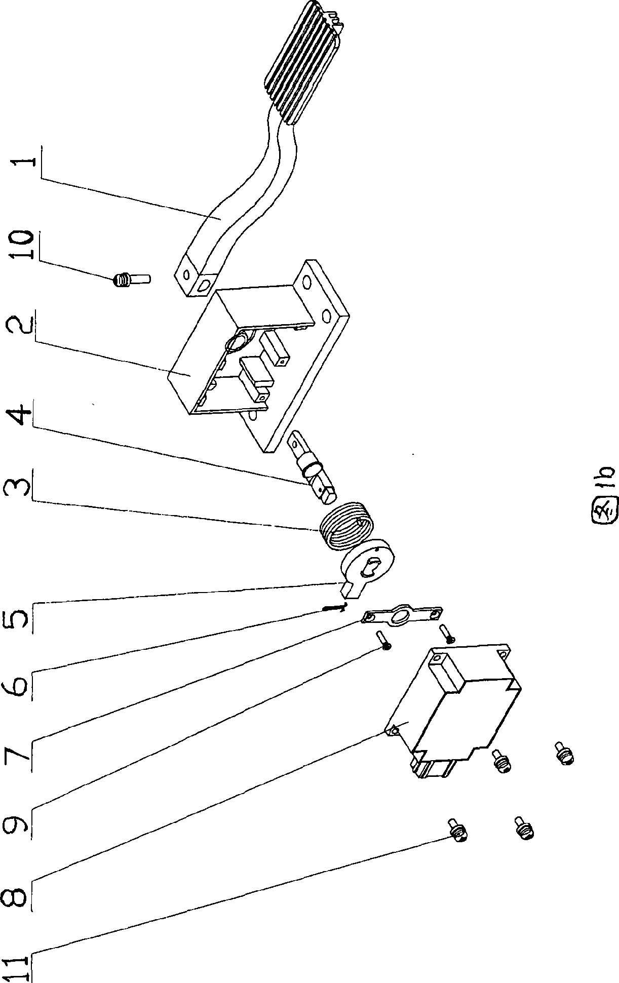
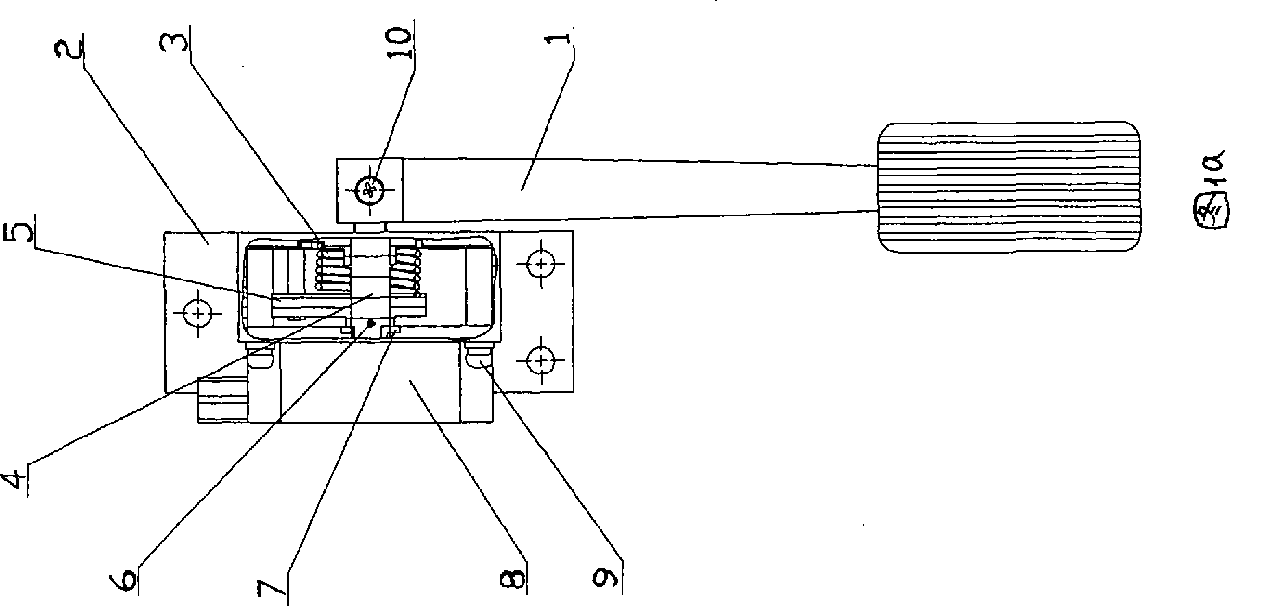
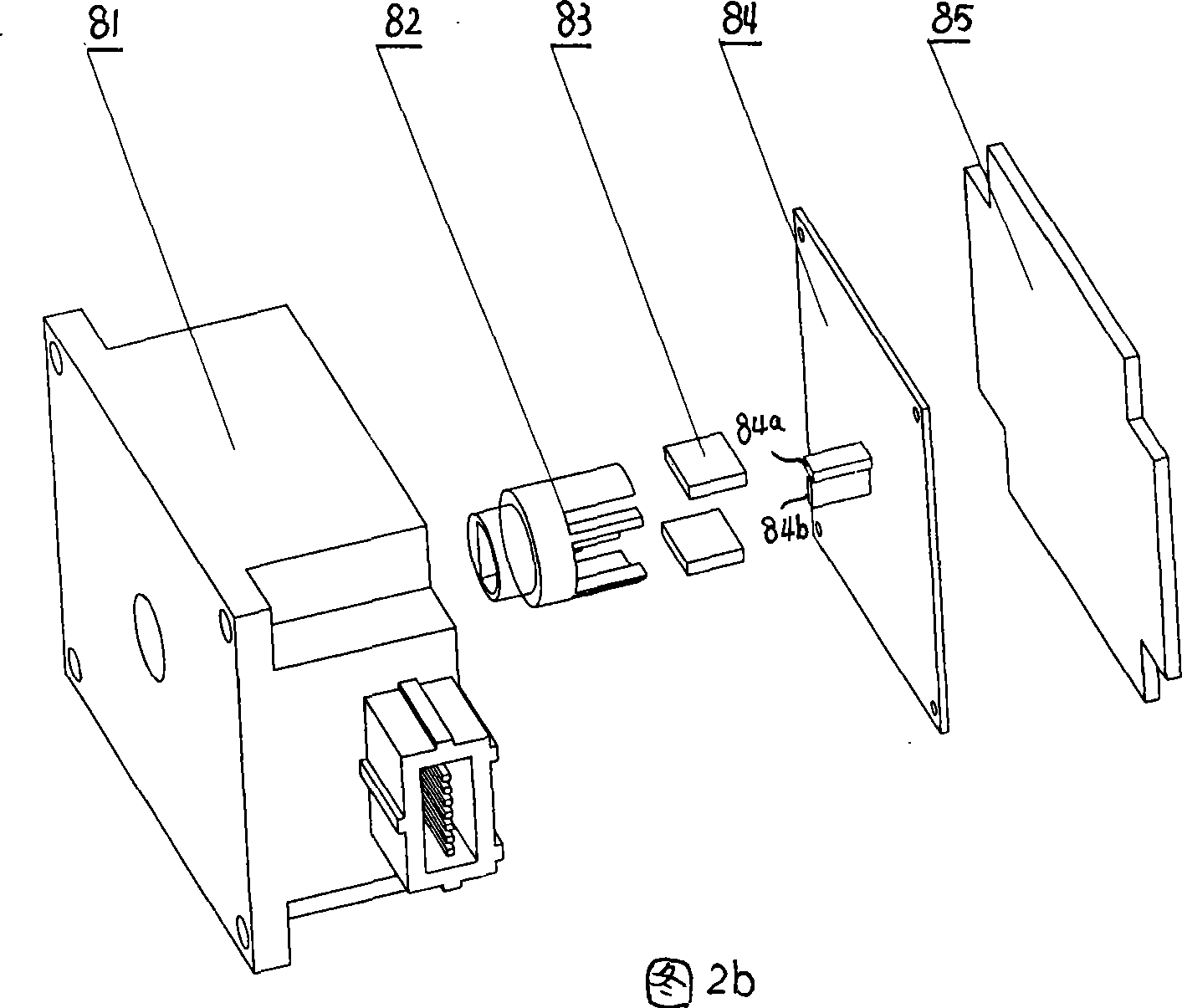
[0016] As shown in Figures 1a and 1b, the pedal 1, return spring 3, center shaft 4, limit plate 5, spring clip 6, pressure plate 7, sensor 8, screw 9, screw 10, and screw 11 are all installed on the body 2. In Fig. 2, the structure of the sensor 8 is as follows: the sensor shaft 82 is arranged on the body 81, and two magnets 83 are fixed on the shaft, and the two-way linear Hall sensors 84a, 84b at a position of 90° are fixed on the circuit board 84 Above, the circuit board is fixed on the body 81, and the Hall sensors 84a, 84b are located within the uniform magnetic field generated by the two magnets 83, the strength of the magnetic field is less than the saturation strength of the Hall sensor; there is also a sensor shaft 82 controlled by the pedal 1 Driving mechanism: the pressure plate 7 is installed on the body 2, the central axis 4 is erected on the limit gap of the body 2 and the opening of the pressure plate 7, and the position inside the pressure plate 7 on the central...


PUM


Abstract

The invention relates to a non-contact intelligent electronic throttle and belongs to an intelligent electronic throttle control assembly for an engine of an automobile. The throttle comprises a sensor structure, a sensor shaft driving mechanism controlled by a throttle pedal, and a singlechip main controller. The sensor structure is as follows: two magnets are fixed on a shaft of the sensor; two linear hall sensors perpendicular to each other are fixed on a circuit board, the circuit board is fixed on a body; and the hall sensors are positioned within a uniform magnetic field generated by the two magnets. The sensor shaft driving mechanism controlled by the throttle pedal is as follows: a pressure pad is arranged on the body, an intermediate shaft is arranged in and suspended by a limit notch of the body and an opening of the pressure pad and is provided with a spring clip, a limit plate and a resetting spring; one end of the resetting spring is connected with the body, while the other end is fixed on the limit plate; when put in place, the resetting spring generates a restoring force; one end, extending out of the body, of the intermediate shaft is connected with the pedal, while the other end is connected with the shaft of the sensor. The throttle has the characteristics of long service life, high precision, high reliability and intelligent control.

Description

technical field [0001] The invention relates to an engine throttle control system, in particular, it belongs to the technical field of an electronic throttle control assembly of an automobile internal combustion engine. Background technique [0002] At present, the accelerator system of the automobile internal combustion engine system is divided into two types: mechanical type and electronic type. The mechanical type uses a steel wire and a lever to connect with the throttle shaft. The driver pulls the steel wire by stepping on the accelerator to control the opening of the throttle and change the output power of the engine. The mechanical throttle is mainly used for the mechanical throttle. The main problem is that it is connected by a steel wire, which is easy to wear and the control is not precise. Now the engine control system is gradually replacing it with an electronic throttle. [0003] At present, most electronic throttles use contact angle sensors, the principle of ...

Claims


Application Information

Patent Timeline
Patent Type & Authority Applications(China)
IPC IPC(8): B60K26/02G05B19/042
Inventor 肖传良张德政张伟杨燕红万里军
Owner SICHUAN HONGGUANG AUTO MACHINERY ELECTRONICS
Why Eureka
Try Eureka