Pipe walking robot and control method thereof

A walking robot, control method technology, applied in chemical instruments and methods, cleaning methods and utensils, special pipes, etc. The effect of practicality and wide application, reliable operation and simple structure

Inactive Publication Date: 2009-05-20
ANHUI UNIVERSITY OF TECHNOLOGY AND SCIENCE
View PDF3 Cites 98 Cited by
  • Summary
  • Abstract
  • Description
  • Claims
  • Application Information

AI Technical Summary

Problems solved by technology

The working principle of this kind of robot is: by converting electrical energy into the mechanical energy of the expansion and contraction of the linkage mechanism, and then into the kinetic energy of the whole device, the whole device can crawl in the pipeline. However, this kind of robot is not only difficult to manufacture, but also adaptable and reliable. The invention patent with the application number 01128568.0 discloses a spring crawling pipeline robot, which uses electromagnetic energy to convert the elastic potential energy of the spring, and then converts it into the kinetic energy of the entire device, so that the device moves
The main purpose of this invention is to realize the movement of the robot in the pipeline, but its structure cannot realize the cleaning of the pipeline, and its adaptability is poor; the invention patent with the patent number of 200710035846.9 discloses a robot that can wriggle in a tiny pipeline robot, but the main function of this robot is to walk in the pipeline, and its structure cannot satisfy the cleaning of the entire pipeline, especially for the circular pipeline.
In short, at present, there are many researches on peristaltic robots, so there are many driving methods, but most of them have slow moving speed, low mechanical efficiency, poor environmental adaptability, etc., so they cannot meet the needs of comprehensive cleaning of pipelines. which limits its further development

Method used


Image

  • Pipe walking robot and control method thereof
  • Pipe walking robot and control method thereof
  • Pipe walking robot and control method thereof

Examples


Embodiment Construction

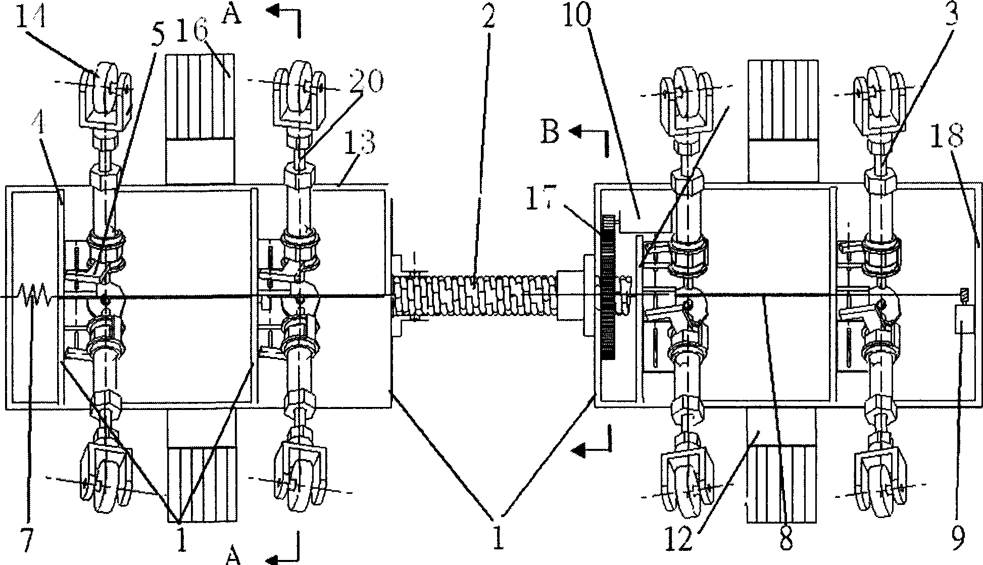
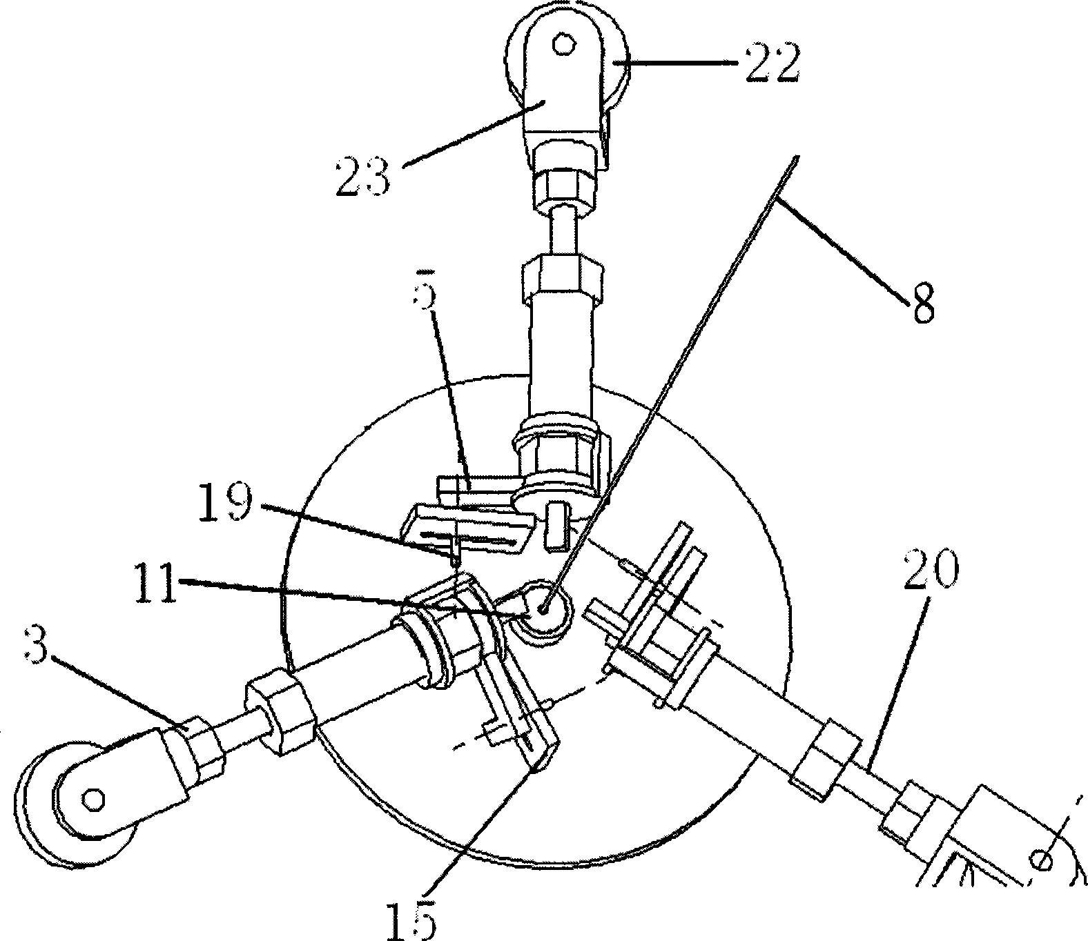
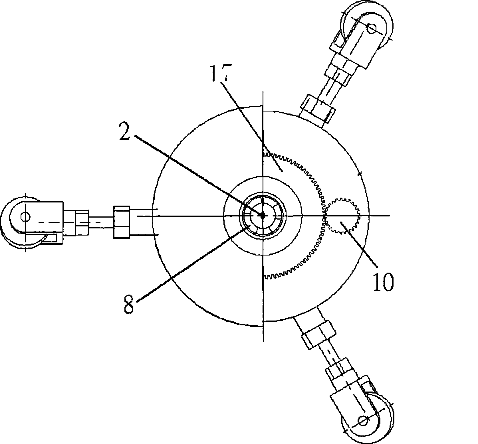
[0030] Below with reference to the accompanying drawings, through the description of the embodiments, the specific embodiments of the present invention, such as the shape, structure, mutual position and connection relationship between the various parts, the role and working principle of the various parts, etc., will be further described. Detailed instructions:

[0031] Such as figure 1 — Figure 5 As shown, the present invention is a pipeline walking robot, and the robot includes a connecting shaft 2, a supporting leg 3, a dial 4, a finger 5, a connecting rope 8, a variable pitch motor 9, a driving motor 10, and a cleaning device 12, The body shell 13, the roller device 14, the connecting rope 8 passes through the dial 4, and is connected with the variable pitch motor 9 fixed inside the body shell 13, and is set as more than one telescopic rotating support leg 3 and the dial 4 connected, the drive motor 10 is connected to the other body shell end 18 through the gear plate 17...


PUM


Abstract

The invention relates to a pipeline cleaning robot applied to industrial field, and also relates to a method for controlling the walking robot. The robot comprises a connection shaft (2), a supporting leg (3), a drive plate (4), a pusher dog (5), a connection rope (8), a variable pitch motor (9), a drive motor (10), a cleaning device (12) and a roller wheel device (14), wherein the connection rope (8) passes through the drive plate (4), and is connected with variable pitch motor (9); the supporting leg (3) which can retractably rotate is connected with the drive plate (4); the drive motor (10) is connected with another frame shell end part (18) through a gear disc (17) and the connection shaft (2); the supporting leg extends out of a frame shell (13), and is contacted with the inner surface of the pipeline; and the cleaning device (12) is arranged on the frame shell (13). With the scheme, the robot is more efficient, can turn a curve smoothly, can be controlled more easily, has the advantages of simple structure and convenient manufacture, and is applicable to pipelines with different diameters.

Description

technical field [0001] The invention relates to the field of industrial robots. More specifically, the invention belongs to a robot that can walk in pipelines and is applied to pipeline cleaning. At the same time, the invention also relates to a control method for the pipeline walking robot. Background technique [0002] Pipelines are widely used in both industrial and civil fields, but difficult problems such as fouling and clogging will inevitably occur during the use of pipelines, especially for some pipelines with relatively narrow spaces, it is impossible for manpower to clean or clean them directly. deal with. With the development of industrial technology, people began to use pipeline robots to clean pipelines with narrow spaces. However, most of the robots currently used have complex structures. For example, the special robots for central air-conditioning are mostly crawler-type, complex in structure, and can only drive and clean in square pipes. At present, there ...

Claims


Application Information

Patent Timeline
Patent Type & Authority Applications(China)
IPC IPC(8): F16L55/32B08B9/049F16L101/12
Inventor 喻全余余静远王善锋赵海荣周帆顾文祥
Owner ANHUI UNIVERSITY OF TECHNOLOGY AND SCIENCE
Why Eureka
Try Eureka