Installation for applying glue to fibers for the production of fiberboard

A technology for manufacturing fibers and fibers, which is applied in the field of a fiber conveying device, can solve problems such as the inability to develop further, and achieve the effect of reducing pollution

Active Publication Date: 2009-06-24
SIEMPELKAMP MASCH & ANLAGENBAU GMBH & CO KG
View PDF4 Cites 5 Cited by
  • Summary
  • Abstract
  • Description
  • Claims
  • Application Information

AI Technical Summary

Problems solved by technology

This hitherto known measure proved to be feasible in principle, but could not be further developed

Method used


Image

  • Installation for applying glue to fibers for the production of fiberboard
  • Installation for applying glue to fibers for the production of fiberboard
  • Installation for applying glue to fibers for the production of fiberboard

Examples


Embodiment Construction

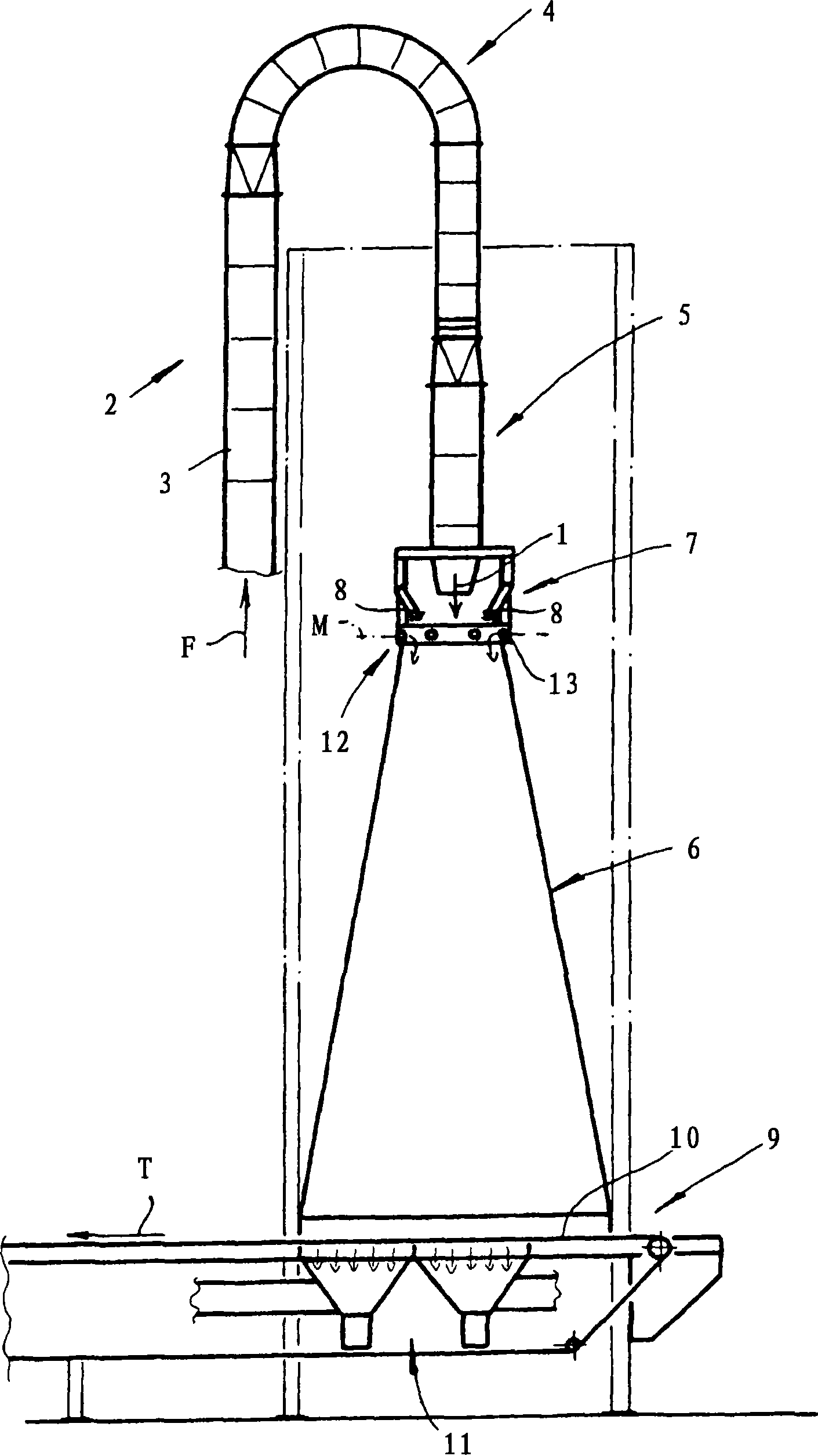
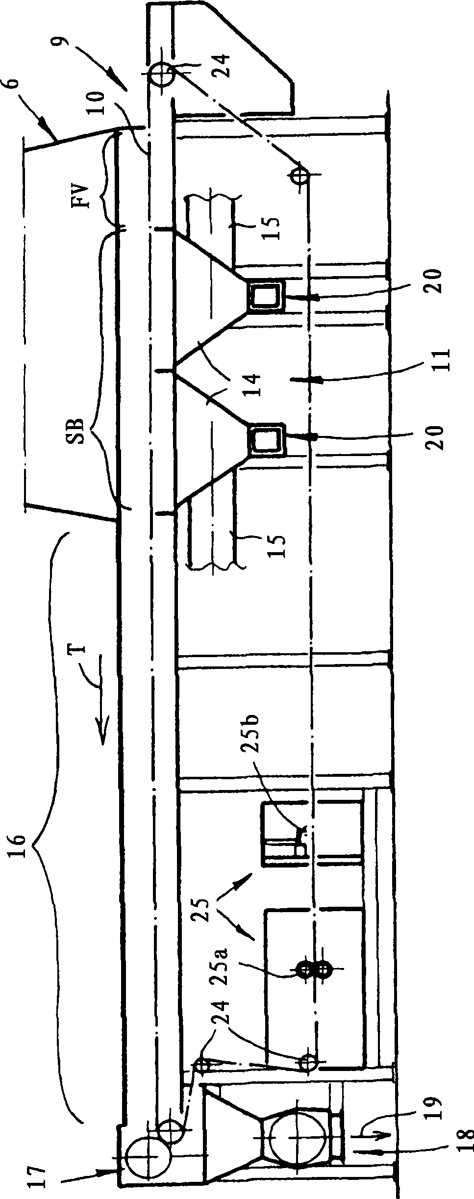
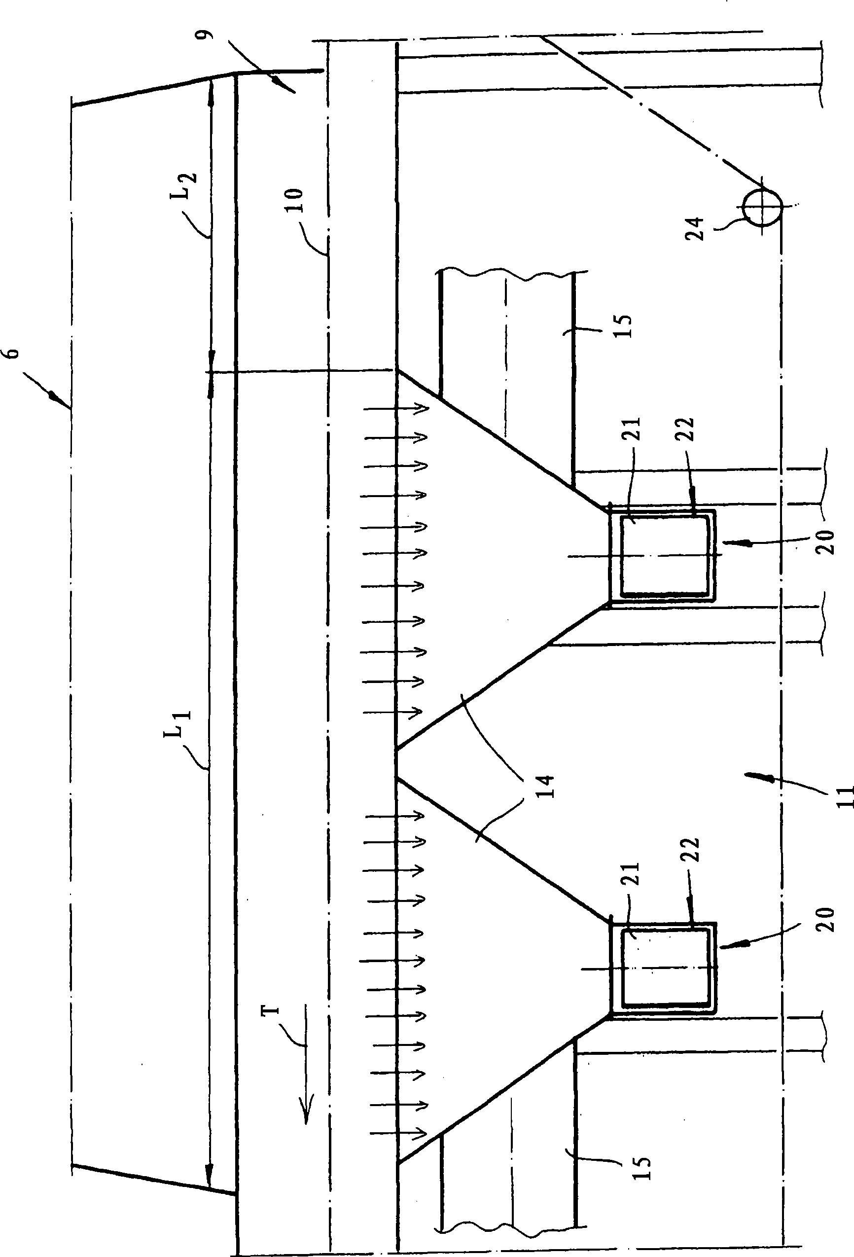
[0016] A plant for gluing fibers for the manufacture of fibreboards, in particular MDF boards, is shown in the drawing. The device is designed for continuous operation and has a fiber feed device 2 comprising at least one fiber feed line 3 to which feed air F can be applied for the fiber feed. This vertically arranged fiber supply line 3 opens via an arcuate 180° fiber deflection line 4 into a likewise vertically oriented fiber discharge line 5 . Arranged downstream of the fiber discharge pipe 5 is a descending shaft 6 which is likewise oriented vertically and has a cross section that widens downwards and thus widens in the direction of descent. A gluing device 7 is arranged between the fiber discharge pipe 5 and the descending shaft 6 and has a nozzle 8 for spraying glue droplets on the fibers 1 exiting the fiber discharging pipe 5 and entering the descending shaft 6 . For this purpose, a plurality of, for example 10 to 20, nozzles are arranged on the nozzle ring which surro...


PUM


Abstract

The invention relates to an installation for applying glue to fibers for the production of fiberboard, especially MDF board or similar wood material board. Said installation comprises a fiber feed unit having at least one fiber feed conduit which opens into a fiber exit tube via a fiber deflection element and receives the air that is used to transport the fibers, a chute which is located downstream of the fiber exit tube, a glue application device which has spray nozzles for spraying the fibers that emerge from the fiber exit tube and enter the chute with drops of glue, and a collection device, located downstream of the chute and having an air-permeable transport belt for collecting and optionally carrying off the fibers and a suction device located below the transport belt for suctioning air from the chute through the transport belt, the suction device having one or more suction boxes to which one or more suction pipes are connected. The installation is characterized in that the suction boxes are configured as cleaning boxes having at least one cleaning device for removing fibers that enter the suction boxes through the transport belt.

Description

technical field [0001] The invention relates to a plant for gluing fibers for the manufacture of fibreboards, in particular MDF boards or similar wood panels, comprising: a fiber conveying device comprising at least one conveying air loadable for fiber conveying A fiber supply pipeline, the fiber delivery pipeline leads to a fiber discharge pipe through a fiber diversion pipe; a descending shaft arranged behind the fiber discharge pipe; a gluing device, the gluing device has a The nozzle of the fiber spray glue drop that exits the fiber discharge pipe and enters the down shaft; and a receiving device arranged behind the down shaft, which includes a gas-permeable conveyor belt for receiving and possibly discharging the fibers and is arranged on the Suction device below the conveyor belt, which is used to draw air through the conveyor belt from the descending shaft, wherein the suction device has one or more suction boxes, to which one or more suction boxes are connected Multip...

Claims


Application Information

Patent Timeline
Patent Type & Authority Applications(China)
IPC IPC(8): B27N1/02B01F5/20
CPCB01F5/205B27N1/029B27N1/0254B27N1/0263Y10T156/15B01F25/721
Inventor D·恩根沃特M·舍勒K·舒尔曼L·塞巴斯蒂安
Owner SIEMPELKAMP MASCH & ANLAGENBAU GMBH & CO KG
Why Eureka
Try Eureka