Compressor and buffering element for fiber compressing apparatus

A buffer element and compression device technology, applied in the field of compressors, can solve the problems of increased noise and wear, and achieve the effect of simple replacement and accurate positioning.

Inactive Publication Date: 2009-08-26
MASCHINENFABRIK RIETER AG
View PDF1 Cites 6 Cited by
  • Summary
  • Abstract
  • Description
  • Claims
  • Application Information

AI Technical Summary

Problems solved by technology

Since the bottom rollers of the output roller pair of the drafting mechanism usually have grooves, there is a danger that the compressor does not perform any relative movement with respect to the bottom rollers an

Method used


Image

  • Compressor and buffering element for fiber compressing apparatus
  • Compressor and buffering element for fiber compressing apparatus
  • Compressor and buffering element for fiber compressing apparatus

Examples


Embodiment Construction

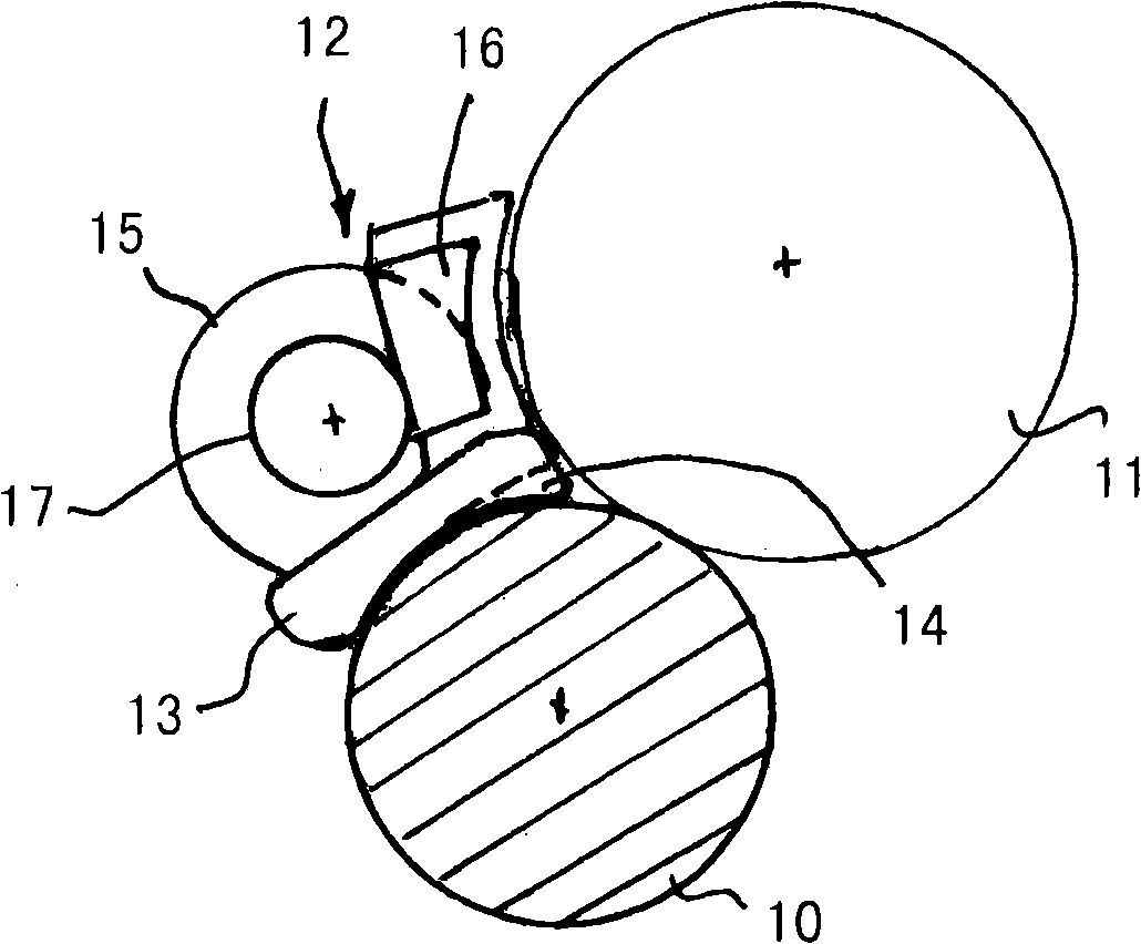
[0013] exist figure 1 shows a pair of output rollers of a drafting mechanism of a spinning machine, in particular a ring spinning machine. The delivery roller pair consists of a driven bottom roller 10 and a top roller 11 which run continuously in the longitudinal direction of the machine. The drafting mechanism includes at least one pair of conveying rollers and a pair of intermediate rollers. Between the middle pair of rollers and the pair of output rollers 10, 11 is the main compression zone. A double apron assembly is typically disposed in the primary compression zone.

[0014] Following the output roller pair 10, 11 is a device such as a ring spindle unit, by which the fiber strand drawn in the drafting mechanism is spun and twisted to produce the yarn. Between the output roller pair 10, 11 and the device for applying textile twist, a mechanical fiber compression device 12 is arranged, which compresses the fiber strands exiting from the delivery roller pair 10, 11 nip ...


PUM


Abstract

The invention relates to a compressor and a buffering element for the fiber compressing apparatus. The compressor for a fiber compressing apparatus configured for a drafting mechanism includes a fiber guidance channel turning thinner in the transferring direction and bearing portions born on outputting lower roller of the drafting mechanism and shaft of a pressing roller, wherein at least one buffering element made from plastic is disposed on the shaft of the pressing roller for bearing the compressor.

Description

technical field [0001] The invention relates to a compressor for a fiber compression device arranged with a drafting mechanism, the compressor having a fiber guide channel tapered in the conveying direction and equipped with a support for supporting on and supporting the output bottom roller of the drafting mechanism Support on the shaft of a hold-down roller. Background technique [0002] It is known (DE 10 2006 015 825 A1) to arrange a compressor without play on a sliding surface on the bottom roller of the delivery roller pair of the drafting mechanism. In the conveying direction, the compressor is supported directly with its bearing surface on the shaft of the pressure rollers which delimit the compression zone. For reasons of wear, the compressor is made of a wear-resistant material, preferably a ceramic material. The shafts of the hold-down rollers are usually made of steel. Since the bottom rollers of the output roller pair of the drafting mechanism usually have gr...

Claims


Application Information

Patent Timeline
IPC IPC(8): D01H5/70D01H5/72
CPCD01H5/72D01H5/26
Inventor K·休伯
Owner MASCHINENFABRIK RIETER AG
Why Eureka
Try Eureka