

Combination stiffening filling pile
A technology of pouring piles and plain concrete piles, which is applied in the field of geotechnical engineering, can solve the problems of low bending resistance and shear resistance, achieve good economic and environmental benefits, reduce the possibility of brittle failure, and ensure safe excavation and use Effect
Active Publication Date: 2010-12-01
ANHUI URBAN CONSTR DESIGN & RES INST
View PDF4 Cites 0 Cited by
- Summary
- Abstract
- Description
- Claims
- Application Information
AI Technical Summary
Problems solved by technology
However, this type of pile only has a section steel skeleton in the pile body. Considering the limitation of the arrangement of section steel in a circular section, it is only suitable for a section with a pile diameter of 300mm-600mm, so the bending and shearing resistance is still low. It must be used in combination with prestressed anchor rods, that is, in pile-anchor systems. It is generally difficult to use cantilever alone, and the maximum applicable foundation pit depth does not exceed 15 meters, and the pile length does not exceed 20 meters, which still has great limitations.
Method used
View moreImage
Smart ImageViewing Examples

Examples
Embodiment 1
Embodiment 2
Embodiment 3
Login to View More PUM
 Abstract
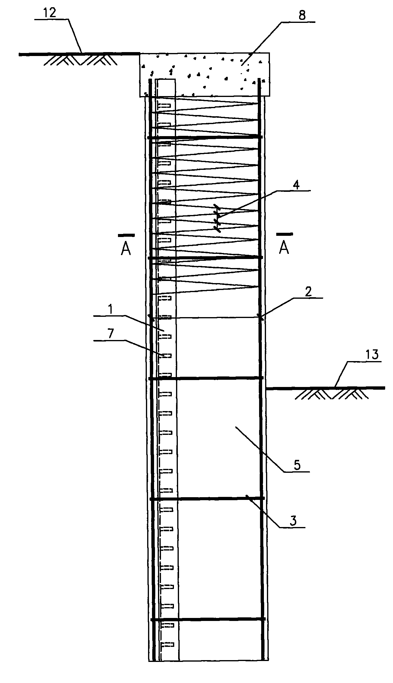
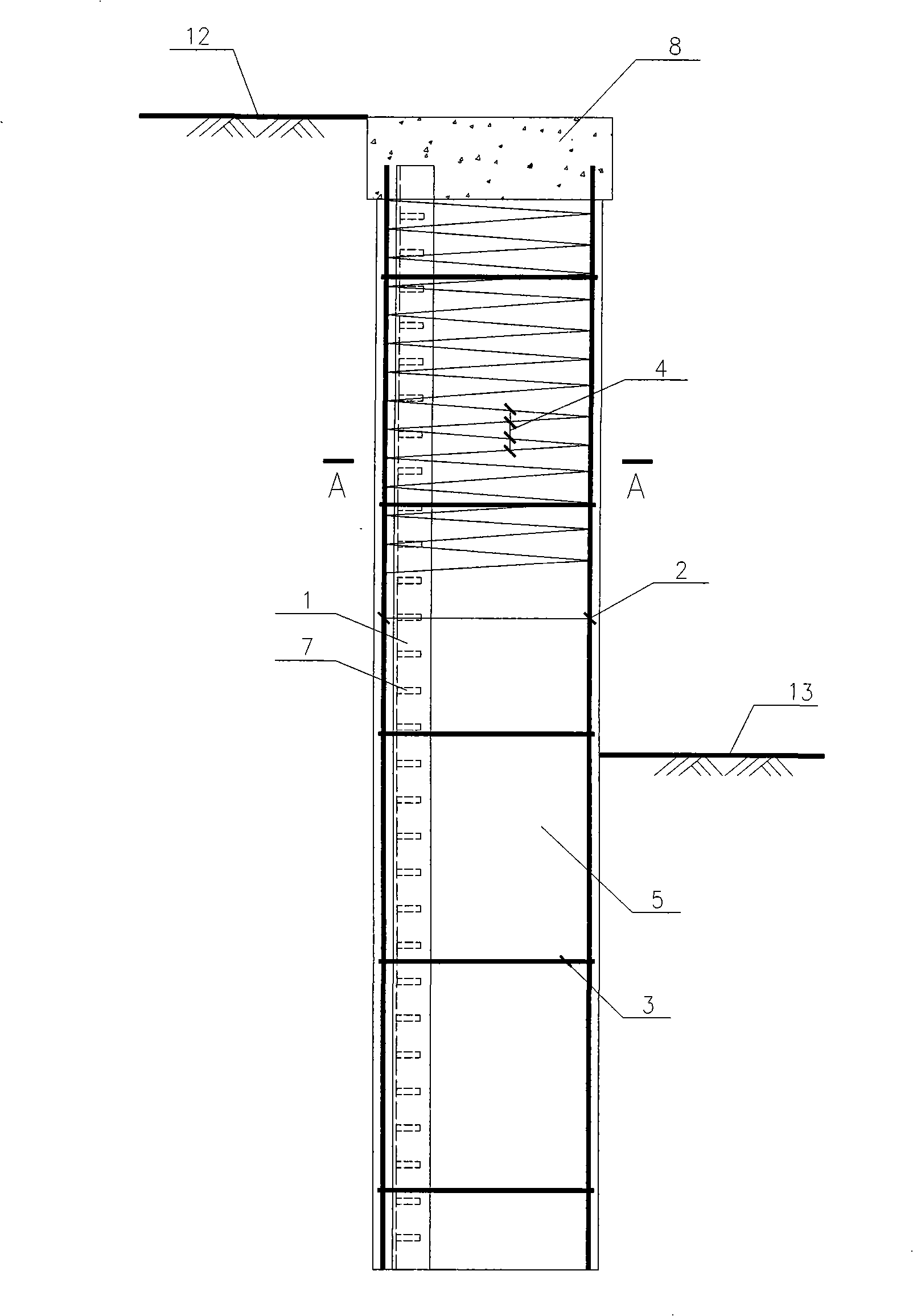
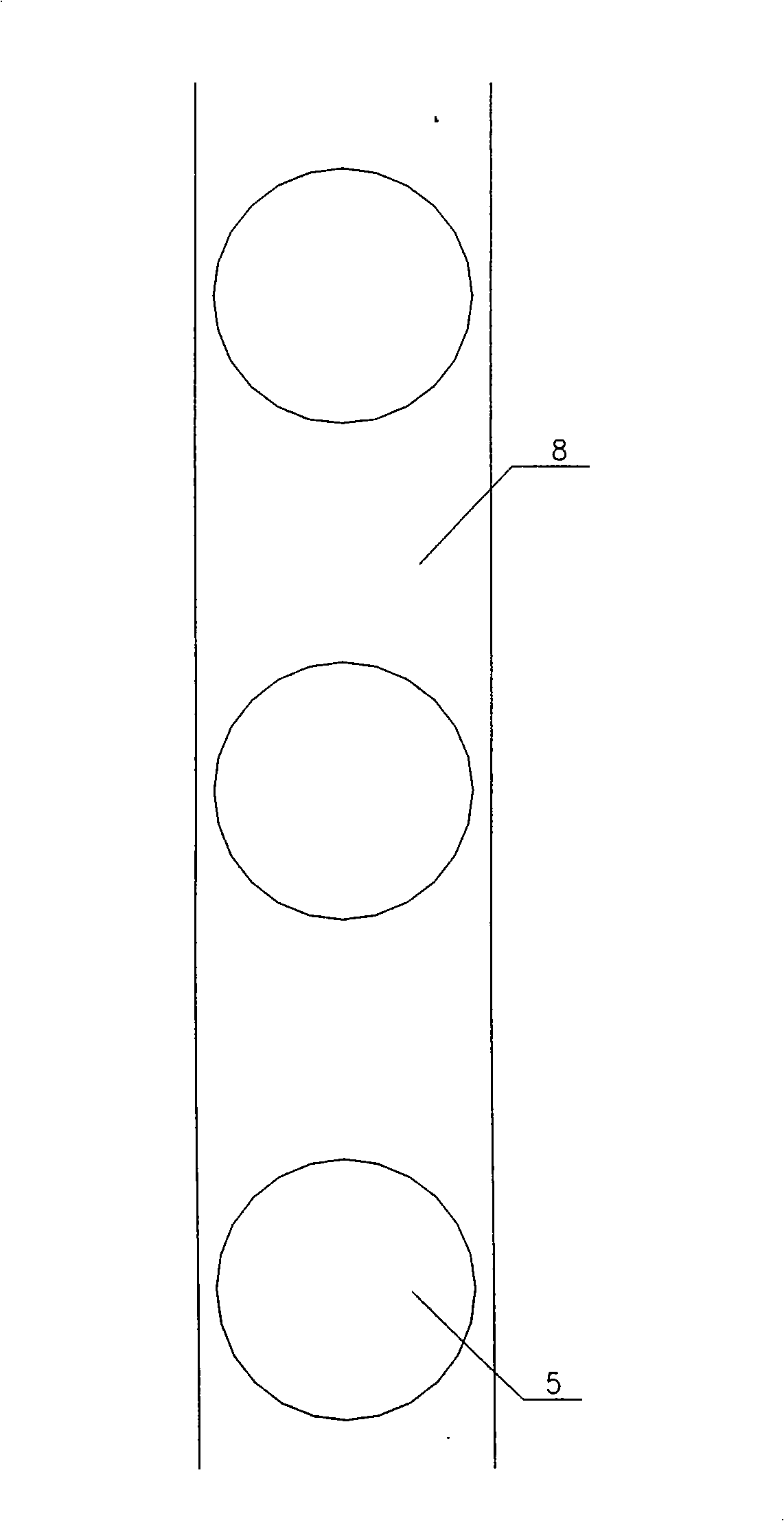
The invention relates to a cantilever type piling supporting structure and a combination stiffening filling pile in a branch anchor type piling supporting structure. The combination stiffening fillingpile comprises a plain concrete pile shaft, a reinforcing cage, a profile steel skeleton which is coaxial with the plain concrete pile shaft wrapping up the reinforcing cage and the profile steel skeleton; the profile steel skeleton comprises more than one channel steels or I-beams; the reinforcing cage comprises longitudinal bars uniformly distributed on the circumference, ring-shaped reinforcing ribs and tie hoops encircling the longitudinal bars; the diameter of the plain concrete pile shaft is 400 to 1200 mm; and the pile length is 5-25 meters; more than one channel steels or the I-beamsand the longitudinal bars of the reinforcing cage are positioned inside a tensile region of the same circumference or in the interior of the reinforcing cage; the channel steels or the I-beam ventralshields are uniformly distributed with shear keys from top to bottom.
Description
Combined reinforced cast-in-situ pile technical field The invention belongs to the field of geotechnical engineering, and in particular relates to a combined stiffened cast-in-situ pile in a cantilever type pile row support structure and an anchor type pile row support structure. Background technique At present, the column-type soil retaining piles used in the foundation pit enclosure in China are mainly mechanically drilled or artificially drilled reinforced concrete pouring piles, which are circular in shape and 400-1200 mm in diameter. Longitudinal bars with a force of more than 1 mm and structural steel bars form a circular steel cage, whose diameter is smaller than the pile diameter, leaving 40-50 mm outside as a protective layer. There are several forms of section reinforcement: Cantilever type, due to the one-sided earth pressure, the tension zone only exists on the side facing the soil, and most of the longitudinal reinforcement is concentrated in the tension zon...
Claims
Login to View More Application Information
Patent Timeline
 Patent Type & AuthorityPatents(China)
IPC IPC(8): E02D17/20E02D5/34
Inventor束冬青李彪蔡敏
OwnerANHUI URBAN CONSTR DESIGN & RES INST