Undervoltage release

An under-voltage release and relay technology, which is applied in the protection of under-voltage or no-voltage, and the switch that operates when the voltage is lower than a predetermined value, can solve the problem of low overall efficiency, complex circuit, and influence on the release. Service life and other issues

Inactive Publication Date: 2010-04-28
CHANGZHOU INST OF TECH
View PDF0 Cites 14 Cited by
  • Summary
  • Abstract
  • Description
  • Claims
  • Application Information

AI Technical Summary

Problems solved by technology

[0004] The electromagnetic undervoltage release of the prior art has the following disadvantages: the relay coil and the electromagnet coil are in different circuits when they are turned on, so the current flowing through the relay coil and the electromagnet coil is often large, so As a result, each coil generates a lot of heat, and the overall efficiency is low, which not only wastes electric energy, but also affects the service life of the release
The existing electromagnetic undervoltage release still has problems such as small starting torque or too complicated circuit

Method used


Image

  • Undervoltage release
  • Undervoltage release

Examples


Embodiment 1

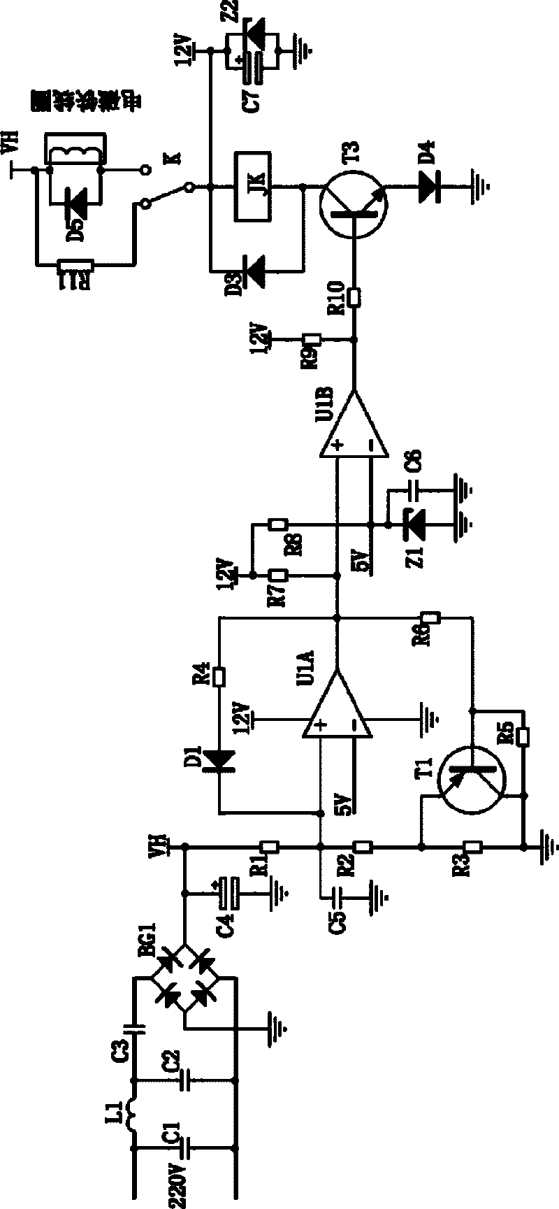
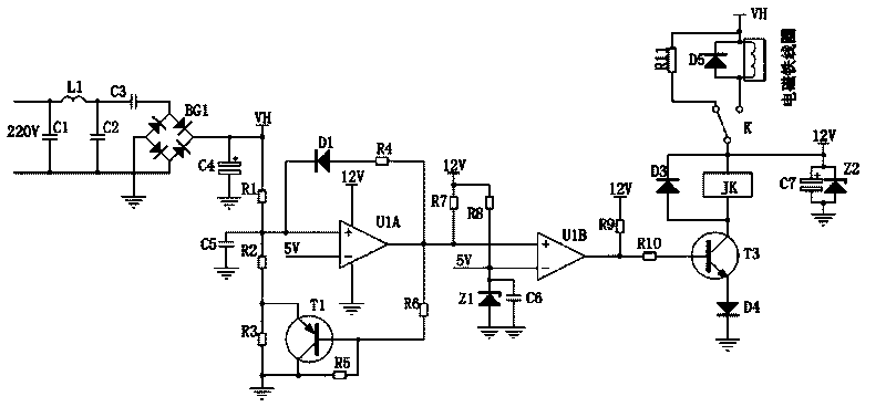
[0017] See figure 1 , the undervoltage release of this embodiment includes: a capacitor charging power-assisted starting power circuit for connecting to the grid, a self-feedback double-limit detection circuit, a relay switching circuit and an electromagnet coil for tripping control; the starting The power output end of the power supply circuit is connected with the power detection input end of the self-feedback double-limit detection circuit, the power input end of the relay switching circuit and the power input end of the electromagnet coil, and the control output end of the self-feedback double-limit detection circuit is connected with the relay switching circuit The control input terminal is connected; the relay switching circuit includes a relay; the relay includes: a relay coil JK, a static contact and two moving contacts; after the grid voltage reaches the pull-in voltage (generally 85% of the standard voltage), it remains at release Voltage (generally 50% of the standa...


PUM


Abstract

The invention relates to an undervoltage release, which comprises a capacitive charging booster type starting power circuit, a self feedback dual-limit detection circuit, a relay switching circuit and an electromagnet coil. The starting power circuit is connected with the self feedback dual-limit detection circuit, the relay switching circuit and the electromagnet coil, and the control output end of the self feedback dual-limit detection circuit is connected with the control input end of the relay switching circuit; the relay switching circuit comprises a relay; when the voltage of a power grid is kept at a release voltage or higher than the release voltage after reaching a pull-in voltage, a relay coil and the electromagnet coil form a serially connected loop; when the voltage of the power grid is lower than the release voltage, the electromagnet coil is in a state of an open circuit; and when the voltage of the power grid restores to the pull-in voltage or higher than the pull-in voltage, the relay coil and the electromagnet coil form a serially connected loop again. The undervoltage release has the advantages of low calorific power, big release instant starting torque, very simple circuit, reliable work, high efficiency and the like.

Description

technical field [0001] The invention relates to an undervoltage release, in particular to an electromagnetic undervoltage release. Background technique [0002] The undervoltage release is the core component of the low-voltage switch. There are two types of working methods for the undervoltage release to drive the ejector rod: electromagnetic type and permanent magnet type. [0003] Compared with the permanent magnet type undervoltage release, the electromagnetic type undervoltage release has a simple circuit. After the power is cut off, the ejector rod has the ability of "self-resetting" under the action of the spring force. [0004] The electromagnetic undervoltage release of the prior art has the following disadvantages: the relay coil and the electromagnet coil are in different circuits when they are turned on, so the current flowing through the relay coil and the electromagnet coil is often large, so As a result, each coil generates a lot of heat, and the overall effic...

Claims


Application Information

Patent Timeline
Patent Type & Authority Applications(China)
IPC IPC(8): H02H3/24H01H83/12
Inventor 吴志祥
Owner CHANGZHOU INST OF TECH
Why Eureka
Try Eureka