Auto-bias voltage stabilizing circuit

A voltage stabilizing circuit and self-bias technology, which is applied in the direction of adjusting electrical variables, control/regulation systems, instruments, etc., can solve the problems affecting the performance parameters of the voltage stabilizing circuit and cannot take into account the process parameters, etc., to achieve the effect of improving performance

Active Publication Date: 2010-06-30
SHANGHAI HUAHONG GRACE SEMICON MFG CORP
View PDF4 Cites 2 Cited by
  • Summary
  • Abstract
  • Description
  • Claims
  • Application Information

AI Technical Summary

Problems solved by technology

However, in the prior art, a fixed voltage is generally used to provide this additional bias voltage. Since the process parameters of integrated circuits are always not completely determined according to a certain statistical distribution, it is impossible for the fixed bias voltage to take into account the variation of process parameters. In all cases, using a fixed bias voltage will make those level shifters or operational amplifiers that are on the marginal parameters not work optimally, thereby affecting the performance parameters of the voltage regulation circuit
[0005] To sum up, it can be known that the voltage stabilizing circuit in the prior art has the following problems. Since it works at a fixed bias voltage and cannot take into account the wide distribution range of process parameters, the level shifter or operational amplifier cannot work in an optimal state and affect the stability. The performance parameters of the piezoelectric circuit, so it is necessary to propose improved technical means to solve this problem

Method used


Image

  • Auto-bias voltage stabilizing circuit
  • Auto-bias voltage stabilizing circuit
  • Auto-bias voltage stabilizing circuit

Examples


Embodiment Construction

[0021] The implementation of the present invention is described below through specific examples and in conjunction with the accompanying drawings, and those skilled in the art can easily understand other advantages and effects of the present invention from the content disclosed in this specification. The present invention can also be implemented or applied through other different specific examples, and various modifications and changes can be made to the details in this specification based on different viewpoints and applications without departing from the spirit of the present invention.

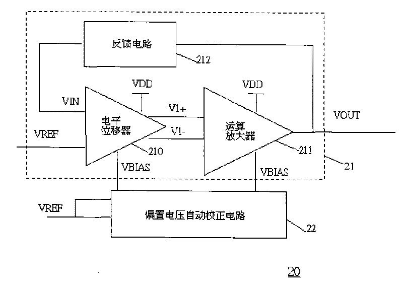
[0022] figure 2 It is a circuit diagram of a self-bias voltage stabilizing circuit of the present invention. Such as figure 2 As shown, a self-bias voltage stabilizing circuit 20 of the present invention includes a main voltage stabilizing circuit 21 and an automatic bias voltage correction circuit 22 , wherein the main voltage stabilizing circuit 21 includes a level shifter 210 , an ope...


PUM


Abstract

The invention discloses an auto-bias voltage stabilizing circuit. The auto-bias voltage stabilizing circuit comprises a first level shifter, a first operational amplifier and a bias voltage automatic correcting circuit, wherein the first level shifter is used for generating a first two-difference voltage; the first operational amplifier is connected with the first level shifter voltage; the firstoperational amplifier amplifies the first two-difference voltage and outputs an output voltage, and the output voltage is simultaneously connected to a feedback circuit; the feedback network samples the output voltage and outputs a feedback voltage to the first level shifter; and the bias voltage automatic correcting circuit is used for converting the variations of the technological parameters ofthe first level shifter into a differential voltage and outputting the differential voltage to the first level shifter and the first operational amplifier, thereby providing a bias voltage. The auto-bias voltage stabilizing circuit does not need to use the fixed bias voltage and can automatically obtain a stable bias voltage by utilizing the bias voltage automatic correcting circuit, so that the output voltage is free from the effects of the technological parameters, and the performance of the voltage stabilizing circuit is enhanced.

Description

technical field [0001] The invention relates to a voltage stabilizing circuit, in particular to a self-bias stabilizing circuit which automatically corrects the bias voltage. Background technique [0002] A voltage stabilizer is a power supply circuit or power supply device that can automatically adjust the output voltage to generate a stable output voltage. Its function is to stabilize the power supply voltage that fluctuates greatly and does not meet the requirements of electrical equipment within its set value range. , so that various circuits or electrical equipment can work normally under the rated working voltage, which can be widely used in electronic computers, precision machine tools, Computed tomography (CT), precision instruments, test devices, elevator lighting, imported equipment and production lines and other places that require a stable voltage of the power supply are also suitable for the end of the low-voltage distribution network where the power supply volt...

Claims


Application Information

Patent Timeline
Patent Type & Authority Applications(China)
IPC IPC(8): G05F1/56
Inventor 杨光军
Owner SHANGHAI HUAHONG GRACE SEMICON MFG CORP
Why Eureka
Try Eureka