Cascade current converter

A technology of converters and converter bridges, which is applied in the field of converters, can solve the problems of difficult realization of dynamic voltage equalization, low output waveform distortion rate, high output waveform distortion rate, etc., to achieve easy modular design, waveform distortion The effect of low rate and small dV/dt

Inactive Publication Date: 2010-10-20
TSINGHUA UNIV
View PDF3 Cites 4 Cited by
  • Summary
  • Abstract
  • Description
  • Claims
  • Application Information

AI Technical Summary

Problems solved by technology

Among them, the device series converter is easy to control, and the multi-phase bridge arms can share the DC side capacitor, which is convenient for realizing DC power transmission and back-to-back operation, but the dynamic voltage equalization is not easy to realize when the devices are connected in series, and the effective The number of levels is small, the output waveform distortion rate is high, and the operating efficiency is slightly low
The H-bridge cascaded converter is based on the cascading of simple units, has more effective levels, lower output waveform distortion rate, and higher operating efficiency, but it does not allow multi-phase bridge arms to share DC side capacitors, so it is not suitable for DC transmission and back-to-back operation

Method used


Image

  • Cascade current converter
  • Cascade current converter
  • Cascade current converter

Examples


Embodiment Construction

[0028] The present invention will be described in detail below in conjunction with the accompanying drawings and embodiments.

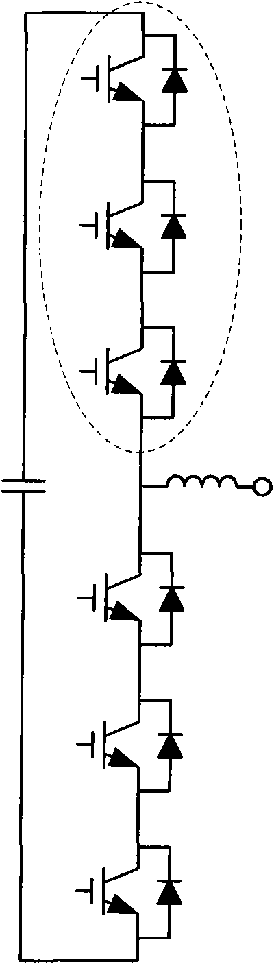
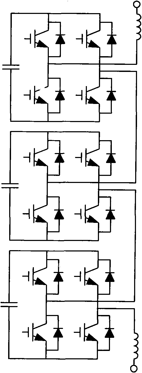
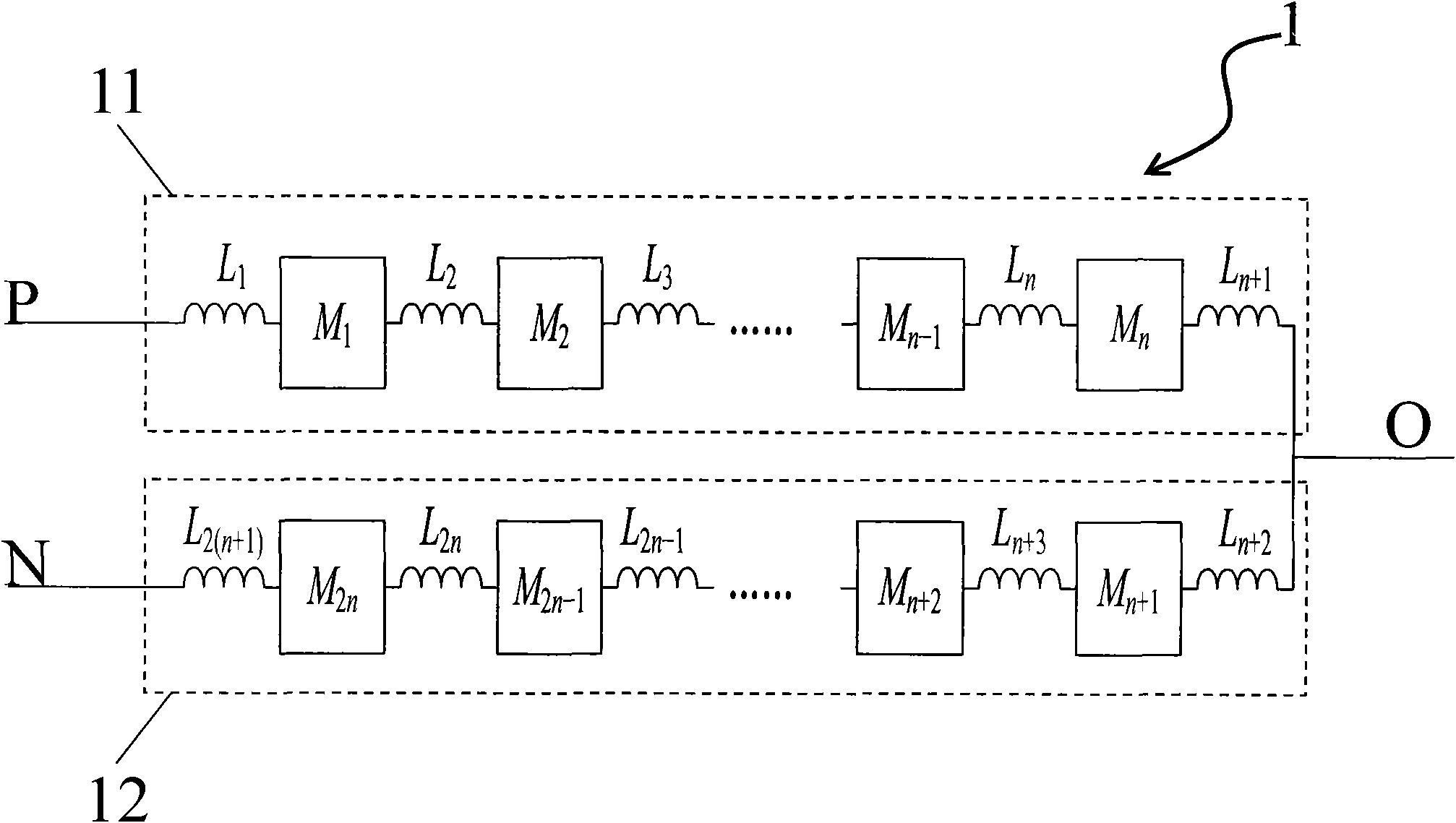
[0029] Such as Figure 3-5 As shown, the present invention includes at least two converter bridge arms 1, wherein each converter bridge arm 1 includes two bridge arm units 11, 12, and the bridge arm unit 11 includes n B-shaped bridges M connected in series j1 (j1=1...n), the bridge arm unit 12 includes n B-shaped bridges M connected in series j2 (j2=n+1...2n). The above n is the number of cascades, n≥1, which is selected according to the actual situation. Two converter bridge arms 1 form a single-phase bridge converter 2 , and three converter bridge arms 1 form a three-phase bridge converter 3 . The converter topology of the present invention is mainly used in the development of voltage source converters of medium and high voltage levels, including pulse power supplies, frequency converters, static var generators, active power filters, direct curre...


PUM


Abstract

The invention relates to a cascade current converter, which is characterized by comprising at least two current converter bridge arms. Each current converter bridge arm comprises a first bridge arm unit and a second bridge arm unit which are connected in series; the series connection point of the first bridge unit and the second bridge unit in each current converter bridge arm is connected with an alternating current outgoing line; the other two ends of the first bridge arm unit and the second bridge arm unit are respectively connected with the anode and the cathode of a direct current bus; the first bridge arm unit comprises n B-shaped bridges (Mj1) connected in series, and the second bridge arm unit comprises n B-shaped bridges (Mj2) connected in series, wherein ji=1...n, j2=n+1...2n, n is a cascade number and n is not less than 1. The invention is mainly used for high and mid-voltage-grade power grids and loads.

Description

technical field [0001] The invention relates to a converter suitable for grids and loads of medium and high voltage levels, in particular to a cascaded converter. Background technique [0002] With the development of medium and high voltage power grids and loads such as new energy power generation and electrified railways, the demand for light direct current transmission systems and back-to-back compensation equipment has greatly increased. Medium and high voltage converters are the key components of these compensation equipments, and their topologies mainly include: devices in series (such as figure 1 shown) and H-bridge cascade type (also known as chain) (such as figure 2 shown). Among them, the device series converter is easy to control, and the multi-phase bridge arms can share the DC side capacitor, which is convenient for realizing DC power transmission and back-to-back operation, but the dynamic voltage equalization is not easy to realize when the devices are conne...

Claims


Application Information

Patent Timeline
Patent Type & Authority Applications(China)
IPC IPC(8): H02M7/48
Inventor 张春朋
Owner TSINGHUA UNIV
Why Eureka
Try Eureka