LED driving circuit and LED lamp

A LED drive and circuit technology, applied in the direction of electric lamp circuit layout, electric light source, electric components, etc., can solve the problems of poor electromagnetic compatibility and other problems, achieve the effect of improving performance, enhancing electromagnetic compatibility, and reducing total harmonic distortion

Active Publication Date: 2010-10-20
OCEANS KING LIGHTING SCI&TECH CO LTD +1
View PDF2 Cites 22 Cited by
  • Summary
  • Abstract
  • Description
  • Claims
  • Application Information

AI Technical Summary

Problems solved by technology

[0004] The purpose of the embodiments of the present invention is to provide an LED driving circuit, aiming to solve the problem of poor electromagnetic compatibility in existing LED driving circuits

Method used


Image

  • LED driving circuit and LED lamp
  • LED driving circuit and LED lamp
  • LED driving circuit and LED lamp

Examples


Embodiment Construction

[0013] In order to make the object, technical solution and advantages of the present invention clearer, the present invention will be further described in detail below in conjunction with the accompanying drawings and embodiments. It should be understood that the specific embodiments described here are only used to explain the present invention, not to limit the present invention.

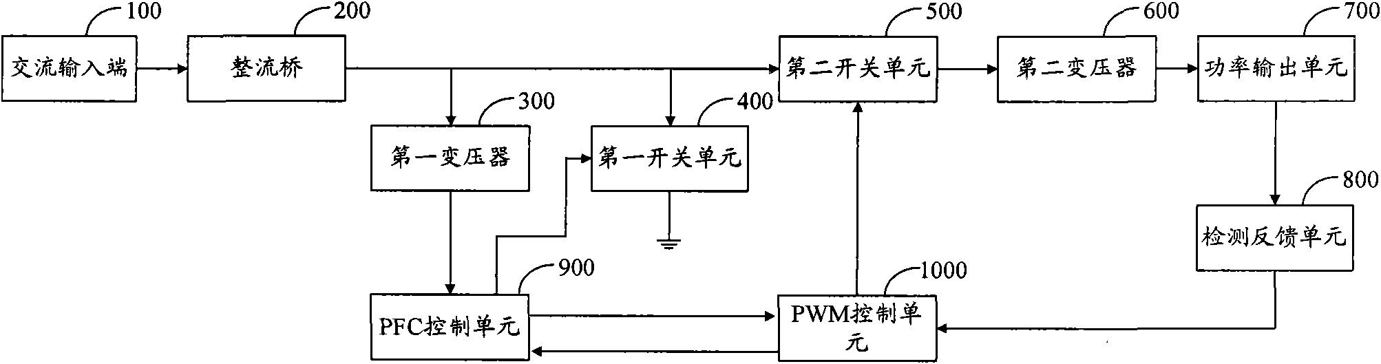
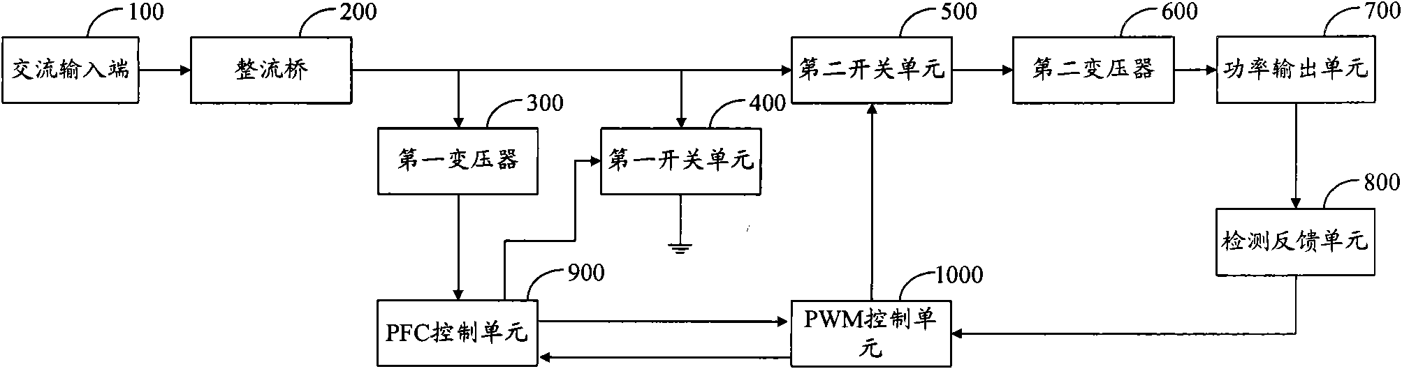
[0014] The PFC control unit of the LED drive circuit provided by the embodiment of the present invention adopts a PFC control chip, and the PFC control chip includes a highly linear multiplier and a THD optimization circuit for reducing the crossover distortion of the AC input current, which can reduce The total harmonic distortion (THD) in the LED driving circuit can enhance the electromagnetic compatibility (EMC) of the LED driving circuit and improve the performance of the LED driving circuit.

[0015] figure 1 The structure of the LED driving circuit provided by the embodiment of the present i...


PUM


Abstract

The invention is applicable to the field of LED lamps, and provides an LED driving circuit and an LED lamp. The LED driving circuit comprises a PFC control unit and a PWM control unit. In the embodiment of the invention, the PFC control unit of the LED driving circuit adopts a PFC control chip; and the PFC control chip comprises a highly linear multiplier and a THD optimal circuit for reducing alternating input current crossover distortion and can reduce the total harmonic distortion (THD) existing in the LED driving circuit so as to enhance the electromagnetic compatibility (EMC) of the LED driving circuit and improve the performance of the LED driving circuit.

Description

technical field [0001] The invention belongs to the field of LED lamps, and in particular relates to an LED driving circuit and an LED lamp. Background technique [0002] LED drive circuit is widely used as the main circuit of LED lamps. The existing LED drive circuit usually includes: AC input terminal, rectifier bridge, PFC (power factor correction) control circuit, PWM control circuit, switch circuit, transformer and power output circuit. . [0003] In the circuit structure of the existing LED drive circuit, a high-frequency filter capacitor is usually installed after the rectifier bridge. When the AC voltage is input near the zero crossing of the AC input terminal, the capacitor cannot be completely discharged, and there is always a residual DC voltage, resulting in AC There is a dead angle in the input current, which is the so-called crossover distortion, which causes the LED drive circuit to have total harmonic distortion (THD), which makes the electromagnetic compati...

Claims


Application Information

Patent Timeline
Patent Type & Authority Applications(China)
IPC IPC(8): H05B37/02H02M1/42H02M5/458
CPCY02B70/126Y02B70/10
Inventor 周明杰肖磊
Owner OCEANS KING LIGHTING SCI&TECH CO LTD
Why Eureka
Try Eureka