Aerosol aspirator

An aspirator and aerosol technology, applied in the field of aerosol aspirators, can solve problems such as the inability to maintain the quality of the solution, that is, aerosol, and thermal deterioration, and achieve the effect of ensuring quantitativeness and quality, and preventing volatilization

Active Publication Date: 2014-04-23
JAPAN TOBACCO INC
View PDF4 Cites 0 Cited by
  • Summary
  • Abstract
  • Description
  • Claims
  • Application Information

AI Technical Summary

Problems solved by technology

Therefore, when the solution contains volatile components, the volatile components in the solution in the tube are volatilized from the solution by the heat from the electric heater, and cause thermal deterioration, and the quality of the solution, that is, the aerosol cannot be maintained stably

Method used


Image

  • Aerosol aspirator
  • Aerosol aspirator
  • Aerosol aspirator

Examples


Embodiment Construction

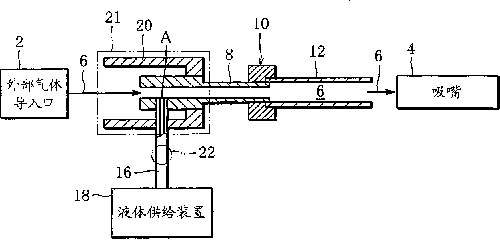
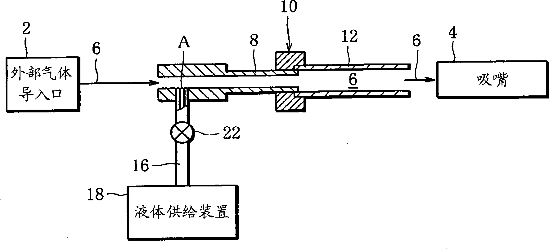
[0022] refer to figure 1 , the aerosol inhaler of the first embodiment has a housing (not shown). The housing has an external air introduction port 2 at its front end, and a suction nozzle 4 protruding from the housing at its rear end. In addition, the casing defines a gas mist generating flow path 6 inside thereof, and the gas mist generating flow path 6 extends from the external air inlet 2 to the suction nozzle 4 . Specifically, in the case of this embodiment, a part of the gas mist generation flow path 6 is formed by the air introduction tube 8 and the tubular ceramic heater 12 .

[0023] The air introduction pipe 8 is formed of stainless steel and has a stepped shape. That is, the air introduction pipe 8 has a large-diameter portion located on the outside-air introduction port 2 side and a small-diameter portion located on the suction nozzle 4 side. The small-diameter end, that is, the downstream end of the air introduction pipe 8 is connected to a ceramic heater 12 vi...


PUM


Abstract

An aerosol inhalator has an aerosol generation passage extending from an ambient air inlet (2) to a mouthpiece (4), a liquid supply device (18) for feeding a predetermined amount of a solution to a feed position (A) in the passage (6), a ceramic heater (12) for heating the solution conveyed from the feed position (A) toward the mouthpiece (4) with a drawn-in flow of air created in the passage (6) by a user's sucking action, thereby causing the solution to evaporate and turn into an aerosol in the passage (6), and a protector provided at least either at a location near the feed position (A) or at a location between the feed position (A) and the liquid supply device (18), the protector having at least one of a radiation cover (2), a cooling device (21) and an open-close valve (22).

Description

technical field [0001] The present invention relates to an aerosol inhaler for supplying medicine, luxury goods, etc. to a user in the form of aerosol. Background technique [0002] Such an aerosol aspirator is disclosed in, for example, Japanese Patent Application Laid-Open No. 2000-510763. The aspirator in this publication has a supply pump for supplying a solution (liquid substance) as an aerosol raw material, and the supply pump is connected to a tube. The tube has an open front end, and the inside of the tube is filled with the solution supplied from the supply pump. In addition, a suction nozzle (mouthpiece) is arranged adjacent to the front end of the tube, and an electric heater surrounding the front end of the tube is also arranged. The electric heater heats and evaporates the solution in the front end of the tube, and the vapor of the solution is ejected from the front end of the tube by itself. The vapor of such a solution is condensed into a mist by contacting...

Claims


Application Information

Patent Timeline
Patent Type & Authority Patents(China)
IPC IPC(8): A61M11/00A61M15/00
CPCB05B7/1686A61M2205/3673A61M2205/3606B05B7/168A61M11/042A61M2205/8206A61M11/041A61M11/007A61M15/06A61M2209/045
Inventor 山田学片山和彦佐佐木宏
Owner JAPAN TOBACCO INC
Why Eureka
Try Eureka