Clothes drier

A drying machine and clothing technology, which is applied to household clothes dryers, washing machines with containers, textiles and papermaking, etc., can solve the restriction of increasing the circulation air volume, cannot fully ensure the air volume for drying, and cannot efficiently dry objects Drying and other problems, to achieve the effect of drying efficiency

Inactive Publication Date: 2011-01-12
TOSHIBA LIFESTYLE PROD & SERVICES CORP
View PDF5 Cites 6 Cited by
  • Summary
  • Abstract
  • Description
  • Claims
  • Application Information

AI Technical Summary

Problems solved by technology

[0008] Therefore, the increase in the circulation air volume is restricted, and the air volume for drying as circulating in the water tank, the dehumidification air duct, and the air supply air duct cannot be sufficiently ensured, and the warm air drying air cannot be sufficiently circulated and supplied to the water tank during the drying operation. In the water tank, there is a problem that the dried object cannot be dried efficiently

Method used


Image

  • Clothes drier
  • Clothes drier
  • Clothes drier

Examples


no. 1 Embodiment approach

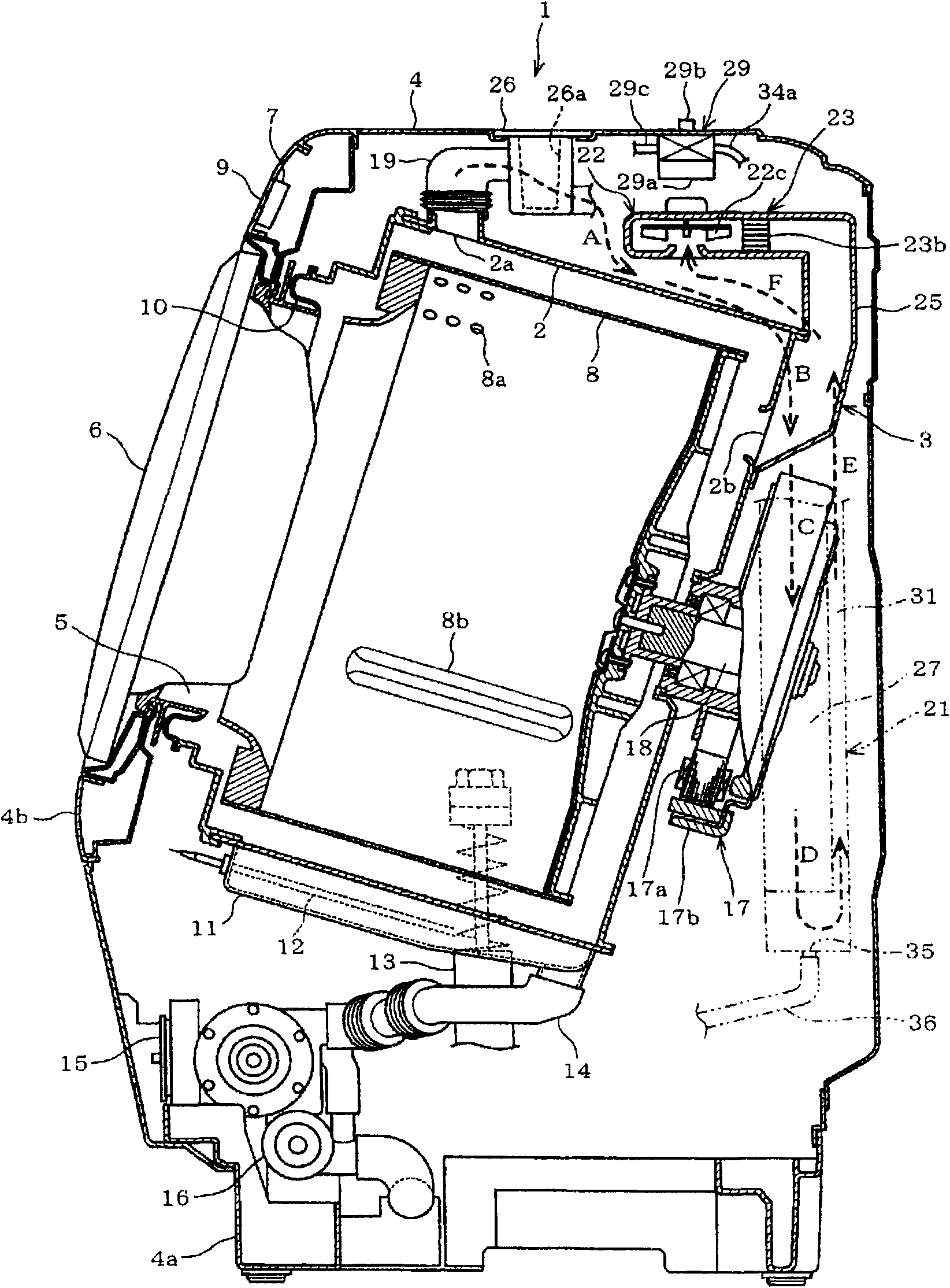
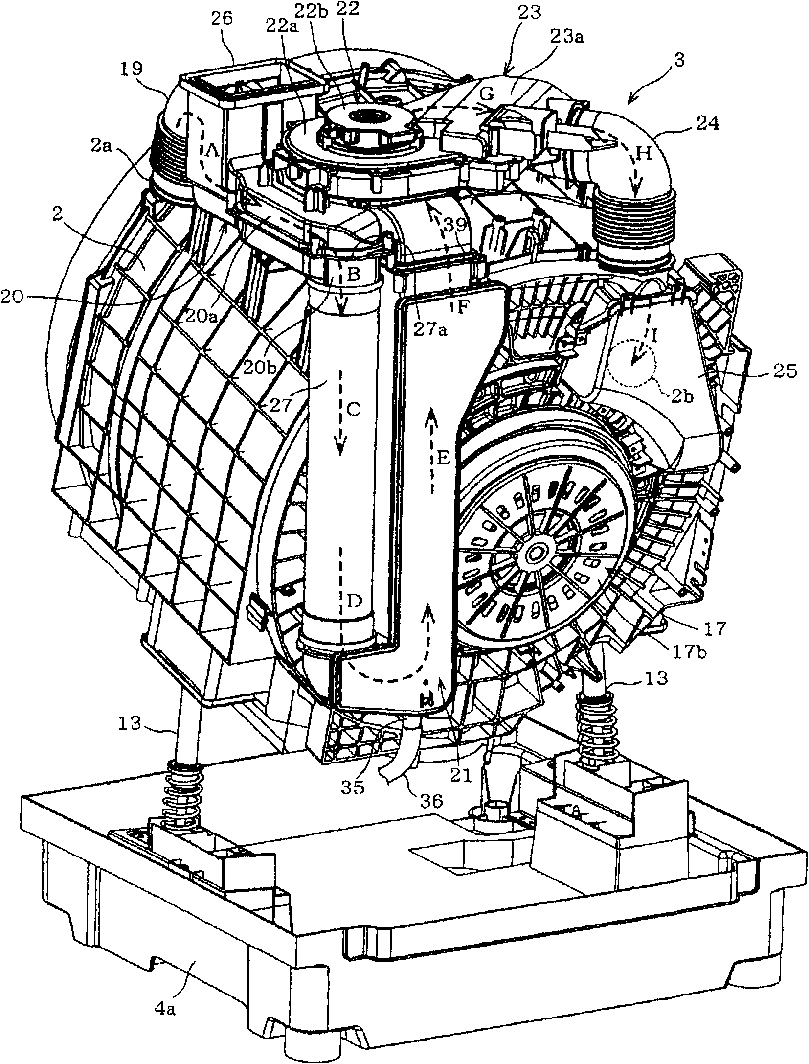
[0027] Hereinafter, for the first embodiment shown by applying the present invention to a drum type washing and drying machine, refer to Figure 1 ~ Figure 4 Be explained. in, figure 2 It is a longitudinal sectional side view showing the overall configuration of the washing and drying machine 1, image 3 It is a perspective view which shows the outer tank 2, the circulation path 3, etc. which are the mechanism part inside a main body mentioned later, and demonstrates the whole structure of the washing-drying machine 1 with reference to these.

[0028] In addition, this washing and drying machine 1 functions as a washing machine when performing a washing operation and a dehydrating operation, and functions as a clothes dryer when performing a drying operation.

[0029] as shown in figure 2 Specifically, the main body 4 that forms the outline of the washing and drying machine 1 is substantially in the shape of a rectangular box, and a bottom plate 4a is provided at the bott...

no. 2 Embodiment approach

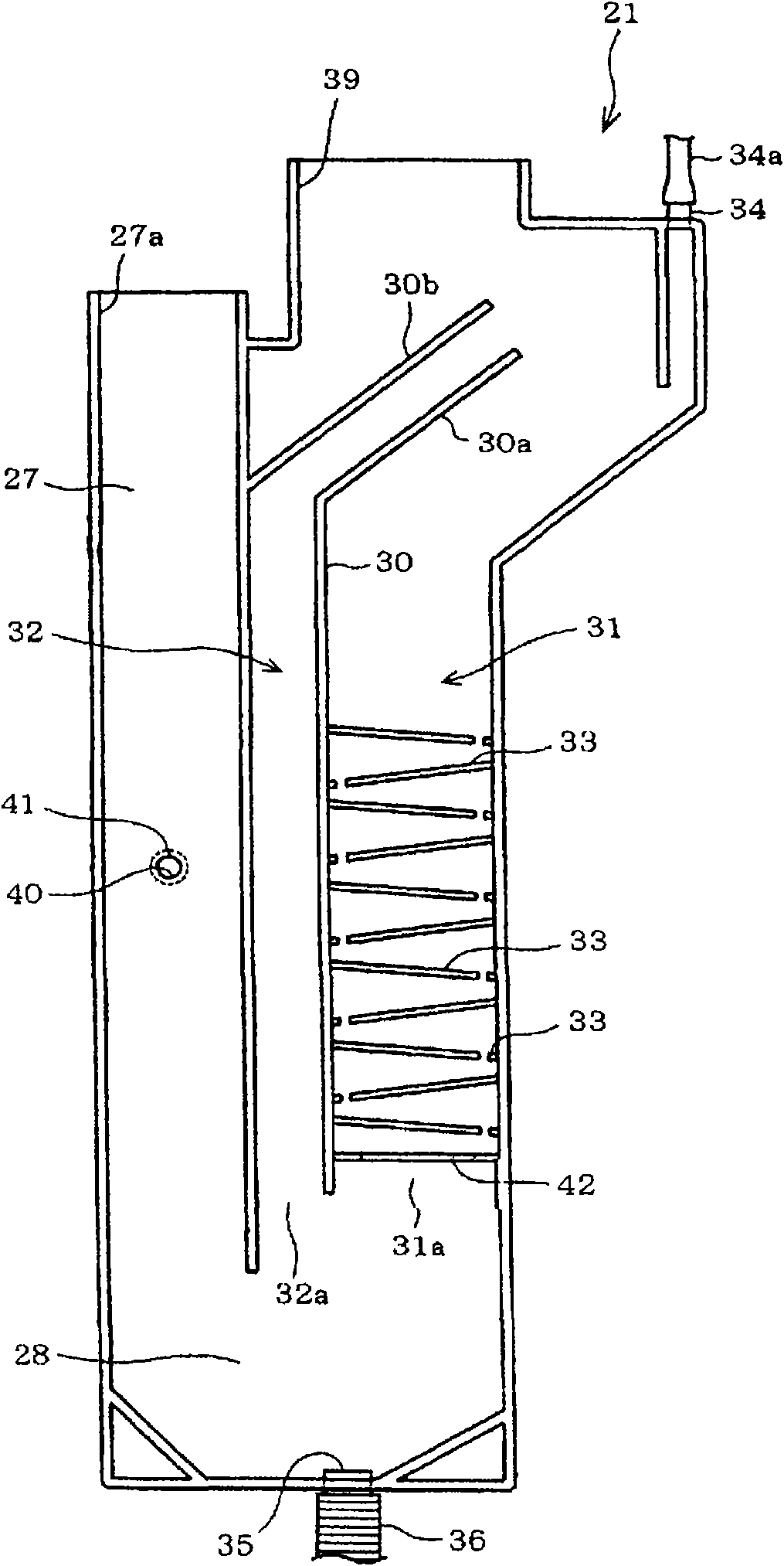
[0115] Figure 5 is the second embodiment of the present invention and figure 1 Quite a graph. as shown in Figure 5 Groundly, the inlet side of the heat exchange unit 21 that constitutes the heat exchanger 31 passage and the branch passage 32 is connected to the vertical pipe 51, and the short-circuit passage 52 that is connected to the drying air outlet 39 side of the heat exchange unit 21 and the heat exchanger 31 is formed. On the side wall top of the drop pipe 51.

[0116] In the present embodiment, since the downpipe 51 is integrally formed with the heat exchange unit 21 and its side wall is a common wall, the short-circuit path 52 can be formed only by forming a communication hole.

[0117] Next, regarding the operation of the drying operation in this embodiment, also refer to the description of the same configuration. figure 2 , image 3 to explain.

[0118] Part of the drying air (dotted arrow C) flowing downward in the drooping tube 51 flows into the short-cir...

no. 3 Embodiment approach

[0128] shown in Figure 6 ~ Figure 10 The third embodiment is characterized in that it is particularly provided with a baffle plate 62 (the passage can be changed) so that the cross-sectional area of ​​the branch passage 32 of the heat exchange unit 61 (corresponding to the heat exchange unit 21 in the first embodiment) can be changed. unit), which will be described in detail below.

[0129] Image 6 is the third embodiment of the present invention and figure 1 Quite a graph. Figure 7 It is an air volume characteristic diagram showing the relationship between the opening degree of the branch passage 32 and the air volume of the drying air flowing into the passage of the heat exchanger 31 and the branch passage 32 . Figure 8 It is a characteristic diagram showing the respective changes in the drying air characteristics and the opening degree of the distribution passage 32 accompanying the progress of the drying operation. Figure 9 It is a characteristic diagram showing t...


PUM


Abstract

The invention relates to a clothes drier which is capable of restraining abnormal raising phenomenon of water droplets and ensuring the circular air volume supplied to a direr chamber in a water-cool dehumidifying heat exchanger, thereby improving the drying efficiency. The clothes drier is provided with a circular passage which is capable of circularly supplying dry wind relative to the direr chamber; a dry wind generating unit is arranged at a middle part of the circular passage; the upstream side of the dry wind generating unit is provided with a heat exchanger (31) and a branch passage (32); the branch passage (32) is parallel to the passage in the heat exchanger (31).

Description

technical field [0001] The present invention relates to a clothes dryer provided with a water-cooled dehumidification heat exchanger in a circulation passage for circulating drying air for drying clothes and the like. Background technique [0002] In the prior art, in order to maximize the efficiency of heat energy for drying, this kind of clothes dryer does not discharge the warm air that heats the air to a predetermined temperature, the so-called dry air, out of the dryer, but circulates it in the circulation path, and dries the air. The wind blows continuously to the to-be-dried object such as clothes to dry. [0003] The basic structure of this clothes dryer is that the circulation passage is connected to the drying air inlet and outlet provided on the front and rear sides of the drying chamber for storing clothes, and a water-cooled dehumidification type heat exchanger is provided in the middle of the circulation passage. An air supply unit such as a wind device and a ...

Claims


Application Information

Patent Timeline
Patent Type & Authority Applications(China)
IPC IPC(8): D06F25/00D06F58/10D06F58/20
CPCD06F58/04D06F58/24D06F58/26F24F1/0059
Inventor 河野源一郎西村博司西胁智马越清辉村濑弘树
Owner TOSHIBA LIFESTYLE PROD & SERVICES CORP
Why Eureka
Try Eureka