Erecting, pushing and sliding method of steel box beam

A technology of steel box girder and sliding, which is applied in the direction of bridge construction, erection/assembly of bridges, bridges, etc., can solve the problems of occupying river structural materials, etc., and achieve the effects of low cost, saving track equipment and labor, and high durability

Active Publication Date: 2011-11-30
CHINA RAILWAY 24TH BUREAU GRP +1
View PDF5 Cites 0 Cited by
  • Summary
  • Abstract
  • Description
  • Claims
  • Application Information

AI Technical Summary

Problems solved by technology

When the beam needs to be replaced, the support method needs to occupy the river channel and a large amount of structural materials

Method used


Image

  • Erecting, pushing and sliding method of steel box beam
  • Erecting, pushing and sliding method of steel box beam
  • Erecting, pushing and sliding method of steel box beam

Examples


Embodiment Construction

[0029] The features of the present invention and other related features will be further described in detail below in conjunction with the accompanying drawings through embodiments, so as to facilitate the understanding of those skilled in the art:

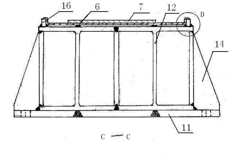
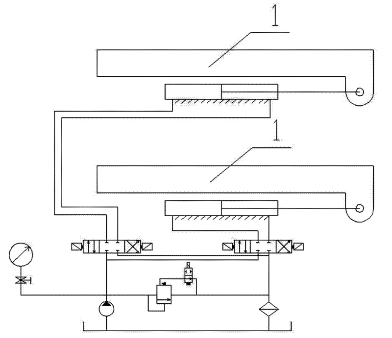
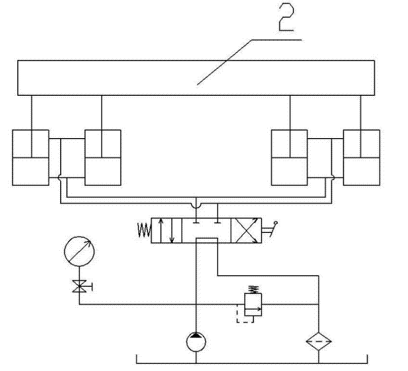
[0030] attached Figure 1-13 The middle marks 1-21 indicate: Skateboard 1, steel box girder transverse bottom surface 2, cloth rubber plate 3, upper supporting plate 4, jacking force device 5, stainless steel plate 6, polytetrafluoroethylene plate 7, "U" Type slideway 8, positioning adjustment bolt 9, lower supporting plate 10, bottom plate 11, H-shaped steel box frame 12, pin seat 13, supporting plate 14, chute 15, rib 16, substrate plate 17, web plate 18, landing beam Use hydraulic jack 19, active pusher or passive pusher 20, steel pad box 21.

[0031] Aiming at the longitudinal movement of large-tonnage steel box girders, the present invention proposes a method of erecting jacking and sliding, using the designed active jacking ...


PUM


Abstract

The invention relates to the technical field of bridge engineering construction, in particular to an erecting, pushing and sliding method of a large-tonnage steel box beam. The method comprises the following steps of: firstly, arranging flat steel gasket boxes at the top of each bridge pier to obtain a plane, mounting a driving pusher or a driven pusher and hydraulic jacks for lifting and fallingthe beam on the plane and moving the steel box beam into the bridge pier; then, starting the driving pusher to drive the steel box beam bodies to slide forwards, simultaneously lifting the hydraulic jacks for lifting and falling the beam to jack the steel box beam after a piston travel is finished, returning the driving pusher to an initial position and falling the hydraulic jacks; and repeating the piston travel to move the steel box beam in place. The method of the invention can be used to safely, rapidly, accurately and continuously realize the longitudinal in place of steel box beams and has controllable pushing and longitudinally moving speed without arranging an upper slideway or a lower slideway so as to save a great amount of rail devices and labor without occupying riverway space.

Description

technical field [0001] The invention relates to the technical field of bridge engineering construction, in particular to a jacking and sliding method for erecting a large-tonnage steel box girder. Background technique [0002] The idea of ​​the jacking method comes from the longitudinal dragging construction method of steel bridges. In the jacking method, the hoist and block are replaced by jacks, and the rollers are replaced by plate sliding bearings. These substitutions ameliorate the stress concentrations due to the impact of the hoist and tackle block at start-up and the wire bearing action of the drum. Since then, the jacking construction technology has been developed and improved rapidly. [0003] The construction principle of the jacking method is to set up a segmental assembly field behind the platform along the longitudinal axis of the bridge, and assemble the beam body in segments. The beam is pushed forward section by section, and the beam is dropped after it i...

Claims


Application Information

Patent Timeline
Patent Type & Authority Patents(China)
IPC IPC(8): E01D21/00
Inventor 周迎选向科刘明杰卢见
Owner CHINA RAILWAY 24TH BUREAU GRP
Why Eureka
Try Eureka