Multistage transmission

一种变速器、速度的技术,应用在齿轮传动装置、带有齿的元件、皮带/链条/齿轮等方向,能够解决不能被最终释放、换挡位置和实际速度不匹配、无法进行换挡等问题

Inactive Publication Date: 2011-03-23
HONDA MOTOR CO LTD
View PDF7 Cites 8 Cited by
  • Summary
  • Abstract
  • Description
  • Claims
  • Application Information

AI Technical Summary

Problems solved by technology

[0012] Since the fitting of the fitting device before the shift is held until the fitting of the fitting device after the shift, when the operation for the next shift is performed before the fitting by the fitting device before the shift is released, the shift drum is Turn, the spring of the lost motion mechanism is further compressed, and the control lever is moved. Due to the further movement of the control lever, the state that the assembly device can be assembled after shifting is released, and the assembly of the assembly device cannot be finally released before shifting, and cannot be performed. shift gears
[0013] However, since the shift drum is turned, a mismatch between the shift position of the shift drum and the actual speed will occur

Method used


Image

  • Multistage transmission
  • Multistage transmission
  • Multistage transmission

Examples


Embodiment Construction

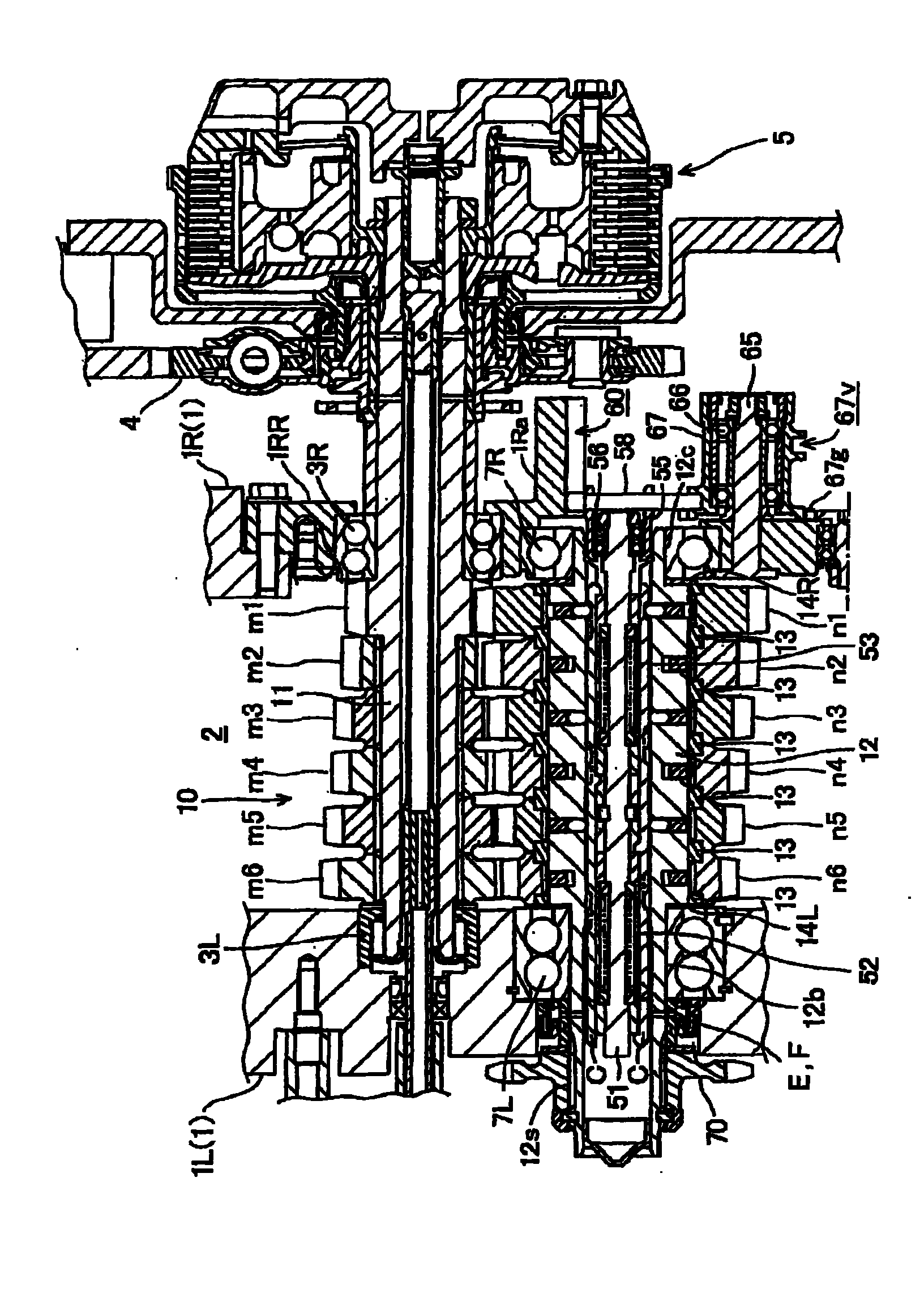
[0073] refer to Figure 1-17 , the present invention will be described below in which a multi-speed transmission 10 is provided in an internal combustion engine installed in a motorcycle.

[0074] figure 1is a cross-sectional view of the multi-stage transmission 10, such as figure 1 As shown, a multi-speed transmission 10 is arranged on a motor housing 1 which also covers the internal combustion engine.

[0075] The engine case 1 is constructed by combining the left engine case 1L and the right engine case 1R, wherein a transmission case 2 is formed by lateral division, and a main gear shaft 11 and an intermediate gear shaft 12 are rotatably supported on the transmission case 2, the gear shafts laterally arranged parallel to each other.

[0076] The main gear shaft 11 is rotatably supported on the side wall of the left engine housing 1L and the side wall 1RR of the right engine housing 1R through each bearing 3L, 3R, and passes through the right bearing 3R. A multi-disc fr...


PUM


Abstract

A multistage transmission includes a lost motion mechanism for regulating the operation for a downward shift in acceleration and for an upward shift in deceleration. Regulating rods are integrally moved with a control rod. A cutout into which a pin can be fitted together with a cam groove of the slidingly touched cam rod is formed corresponding to each cam groove in the regulating rods. The cutout of the regulating rods corresponding to the cam groove of the cam rod for normal rotation is formed longer than the corresponding cam groove on the reverse side to a moving direction of the control rod in an upward shift in a state in which shifted speed is established. The cutout of the regulating rods corresponding to the cam groove of the cam rod for reverse rotation is formed longer than thecorresponding cam groove on the reverse side to a moving direction.

Description

[0001] Cross References to Related Applications [0002] This application claims priority under 35 USC 119 to Japanese Patent Application 2009-178504, filed July 31, 2009, and Japanese Patent Application 2009-199219, filed August 31, 2009, the entire contents of which are at This is incorporated by reference. technical field [0003] The present invention relates to a multi-stage transmission in which a plurality of driving gears and a plurality of driven gears are supported on mutually parallel gear shafts in a constant meshing state at each speed. Background technique [0004] In the constant mesh multi-stage transmission, the driving gear set or the driven gear set is fixed on the gear shaft, and the other gear set is rotatably supported on the gear shaft. A rotating shaft of gears that enables gear changes. [0005] The applicant has known such a construction in which the lost motion mechanism comprises a shifting drive which performs the shifting by means of a switchi...

Claims


Application Information

Patent Timeline
Patent Type & Authority Applications(China)
IPC IPC(8): F16H3/10
CPCF16H2063/3096F16H3/083Y10T74/19279Y10T74/19219
Inventor 松本真也
Owner HONDA MOTOR CO LTD
Why Eureka
Try Eureka