Non-isolated DC-DC converter assembly

A technology of DC converters and converters, applied in the direction of conversion of DC power input to DC power output, output power conversion equipment, conversion equipment without intermediate conversion to AC, etc., can solve the problem of pulsating current, DC-DC converter The output voltage cannot be adjusted, reducing system availability and other problems, so as to avoid EMI problems, large volume and cost, and high cost

Inactive Publication Date: 2011-05-11
ABB RES LTD
View PDF5 Cites 8 Cited by
  • Summary
  • Abstract
  • Description
  • Claims
  • Application Information

AI Technical Summary

Problems solved by technology

The output voltage of the DC-DC converter proposed in US2004 / 0164557 cannot be regulated
In operating situations where the source of the DC-DC converter generates a voltage lower than the level requested by the load, the converter must be switched off, thus reducing system availability
Also, because the DC-DC converter of US2004 / 0164557 includes a buck-boost converter, the source will suffer from pulsating current

Method used


Image

  • Non-isolated DC-DC converter assembly
  • Non-isolated DC-DC converter assembly
  • Non-isolated DC-DC converter assembly

Examples


Embodiment Construction

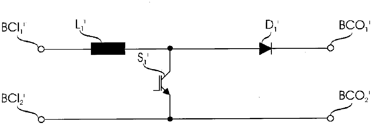
[0016] figure 1 A conventional boost converter suitable for boosting an input voltage to a higher output voltage is shown. The boost converter includes an inductor L 1 ’, diode D 1 ’ and the controllable switch S 1 '. The boost converter has a first input terminal BCI 1 ’, the second input terminal BCI 2 ', the first output terminal BCO 1 ’ and the second output terminal BCO 2 '. Input DC voltage through the first input terminal BCI 1 ’ and the second input terminal BCI 2 'enter. First input terminal BCI 1 ’ is the positive terminal while the second input terminal BCI 2 ’ is the negative terminal. The output voltage appears at the first output terminal BCO 1 ’ and the second output terminal BCO 2 ’, the first output terminal BCO 1 ’ is the positive terminal while the second output terminal BCO 2 ’ is the negative terminal.

[0017] Inductor L 1 ’ and the diode D 1 ’ connected in series at the first input terminal BCI of the boost converter 1 ’ and the firs...


PUM


Abstract

The invention relates to a solar power station comprising a non-isolated DC-DC converter assembly, and the non-isolated DC-DC converter assembly comprises a boost converter and a converter connected together in a specific way.

Description

technical field [0001] The present invention relates to a non-isolated direct current-direct current (DC-DC) converter assembly. More specifically, the present invention relates to a non-isolated DC-DC converter assembly suitable for use with photovoltaic cell components. Background technique [0002] Two main types of photovoltaic inverters can be found today, isolated and non-isolated photovoltaic inverters. Due to galvanic isolation, the first category of photovoltaic inverters allows grounding of the photovoltaic panel terminals, which is mandatory in some countries due to safety concerns related to leakage currents. Grounding the negative photovoltaic panel terminal is also advantageous because it mitigates photovoltaic panel degradation problems. Even in countries where galvanic isolation is not mandatory, the presence of a transformer is necessary when using some specific photovoltaic cell technologies such as thin film. However, when this additional element, ie th...

Claims


Application Information

Patent Timeline
Patent Type & Authority Applications(China)
IPC IPC(8): H02M3/06H02M3/10
CPCH02M3/158
Inventor 莱昂纳多-奥古斯托·塞尔帕米科·帕基宁弗朗西斯科·卡纳莱斯格拉尔多·埃斯科巴尔安东尼奥·科恰
Owner ABB RES LTD
Why Eureka
Try Eureka