Brake device for controlling the pressure applied to a brake cylinder in a pneumatic braking system

A technology of braking device and braking system, applied in the direction of braking transmission device, brake, braking component, etc., can solve the problem of loss of braking force, etc., and achieve the effect of large adhesion utilization rate

Inactive Publication Date: 2011-06-08
KNORR BREMSE SYST FUR SCHIENENFAHRZEUGE GMBH
View PDF1 Cites 4 Cited by
  • Summary
  • Abstract
  • Description
  • Claims
  • Application Information

AI Technical Summary

Problems solved by technology

However, a possible braking force is thus lost, which could still be fully utilized until the adhesion limit is reached.

Method used


Image

  • Brake device for controlling the pressure applied to a brake cylinder in a pneumatic braking system
  • Brake device for controlling the pressure applied to a brake cylinder in a pneumatic braking system

Examples


Embodiment Construction

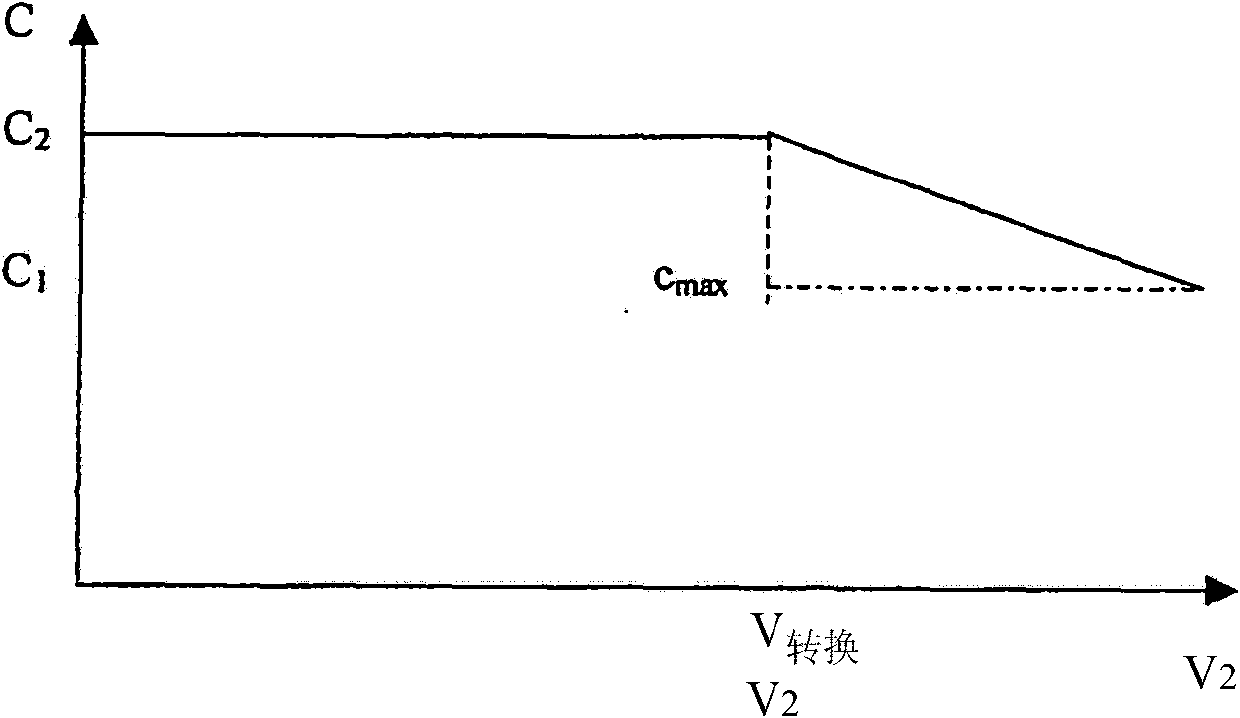
[0020] according to figure 1 From the limit speed V max >V 转换 (VU mschalt ) to increase the brake pressure C used to load the brake cylinder from a low brake pressure C1 to a higher brake pressure C2 in order to achieve a higher adhesion utilization at low speeds and at higher speeds Undesired release of the anti-slip device is prevented at the same time. Limit speed V 转换 In the example it is 200 km / h. However, from reaching the limit speed V 转换 From now on, the brake pressure C2 is not increased stepwise to a higher brake pressure C2 (dashed line), but according to the maximum adhesion utilization. For that matter upon reaching the limit speed V 转换 , the brake pressure C increases linearly with the speed that continues to rise. Because the international traffic standard stipulates that the maximum adhesion utilization should occur in order to improve the braking performance of the vehicle. As shown in the diagrammatic representation, this results in a maximum permiss...


PUM


Abstract

The invention relates to a brake device for controlling the pressure applied to a brake cylinder in a pneumatic braking system, having a pneumatic pilot unit (1) located in a valve housing (3) for actuating a relay valve (2) for controlling the brake pressure (C), wherein a balance beam (8) disposed therebetween and transmitting actuating force acts together with means for displacing a counterbearing (10) as a function of the load state of the automobile, said brake device displacing the counterbearing (10) continuously in proportion to a brake pressure-speed characteristic curve utilizing the maximal permissible adhesion during braking from a high speed.

Description

technical field [0001] The invention relates to a brake device for controlling the pressure loading of a brake cylinder in a pneumatic brake system, which has a pneumatic pilot control unit arranged in a valve housing for actuating a relay valve to control the brake pressure, wherein the centrally arranged balancing beam transmitting the steering force cooperates with the device for moving the support (Widerlager) depending on the load state of the vehicle, these devices are continuous during high-speed braking, especially emergency braking The carrier is moved according to the brake pressure-speed-characteristic curve which makes full use of the maximum permissible adhesion. Background technique [0002] The field of use of the invention extends to pneumatic brake systems, in particular for rail vehicles, in which the electronic control makes the difference between the brake cylinder demand and the brake pressure in the brake cylinder The transfer coefficient has a load co...

Claims


Application Information

Patent Timeline
Patent Type & Authority Applications(China)
IPC IPC(8): B60T13/66
CPCB60T17/228B60T17/04B60T13/665B60T8/17B60T13/26B60T13/66
Inventor 马塔乌斯·恩格尔布莱赫特马克-奥利弗·赫尔登马丁·黑勒
Owner KNORR BREMSE SYST FUR SCHIENENFAHRZEUGE GMBH
Why Eureka
Try Eureka