Control arrangement in piston engine

A piston engine and control device technology, applied to valve drive devices, engine components, machines/engines, etc., can solve problems such as prolonged intake valve opening time

Active Publication Date: 2014-03-12
WARTSILA FINLAND OY
View PDF4 Cites 0 Cited by
  • Summary
  • Abstract
  • Description
  • Claims
  • Application Information

AI Technical Summary

Problems solved by technology

Another solution is to provide a delay in the closing of the intake valves so that the intake valves can be opened longer if required

Method used


Image

  • Control arrangement in piston engine
  • Control arrangement in piston engine
  • Control arrangement in piston engine

Examples


Embodiment Construction

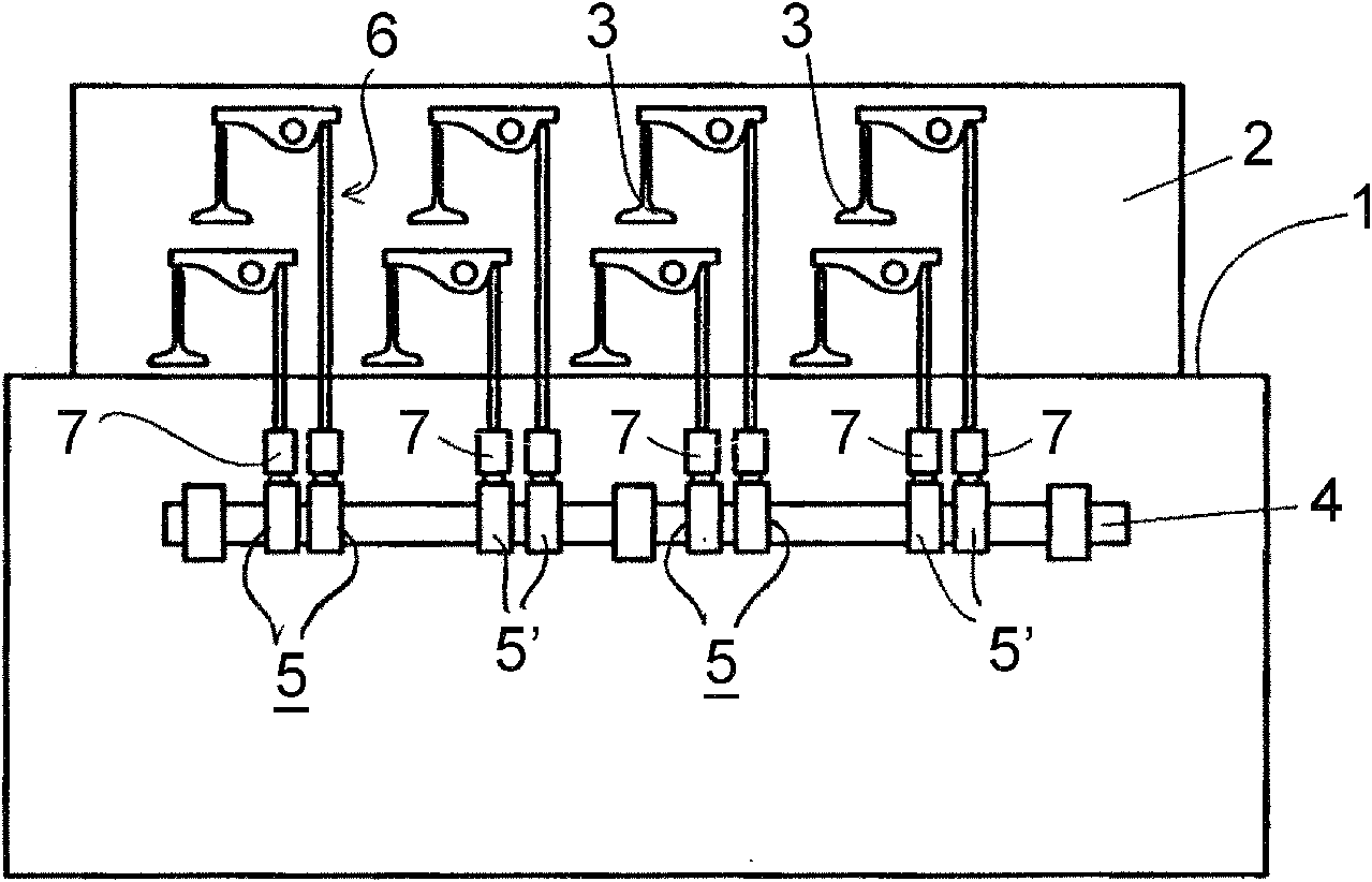
[0019] figure 1 A schematic diagram of the piston engine 1 is shown to a degree relevant to the understanding of the present invention. The gas exchange of cylinders (not shown) in the piston engine 1 is performed under the control of gas exchange valves (ie, intake valves and exhaust valves) located on the cylinder head 2. Only the intake valves 3 are shown and they are operated by a valve train 6, which is usually guided by the cam profile 5'of the cam gear 5 arranged on the camshaft 4 of the engine. The force transmission connection between each valve mechanism 6 and the corresponding cam mechanism 5 is realized by the control device 7.

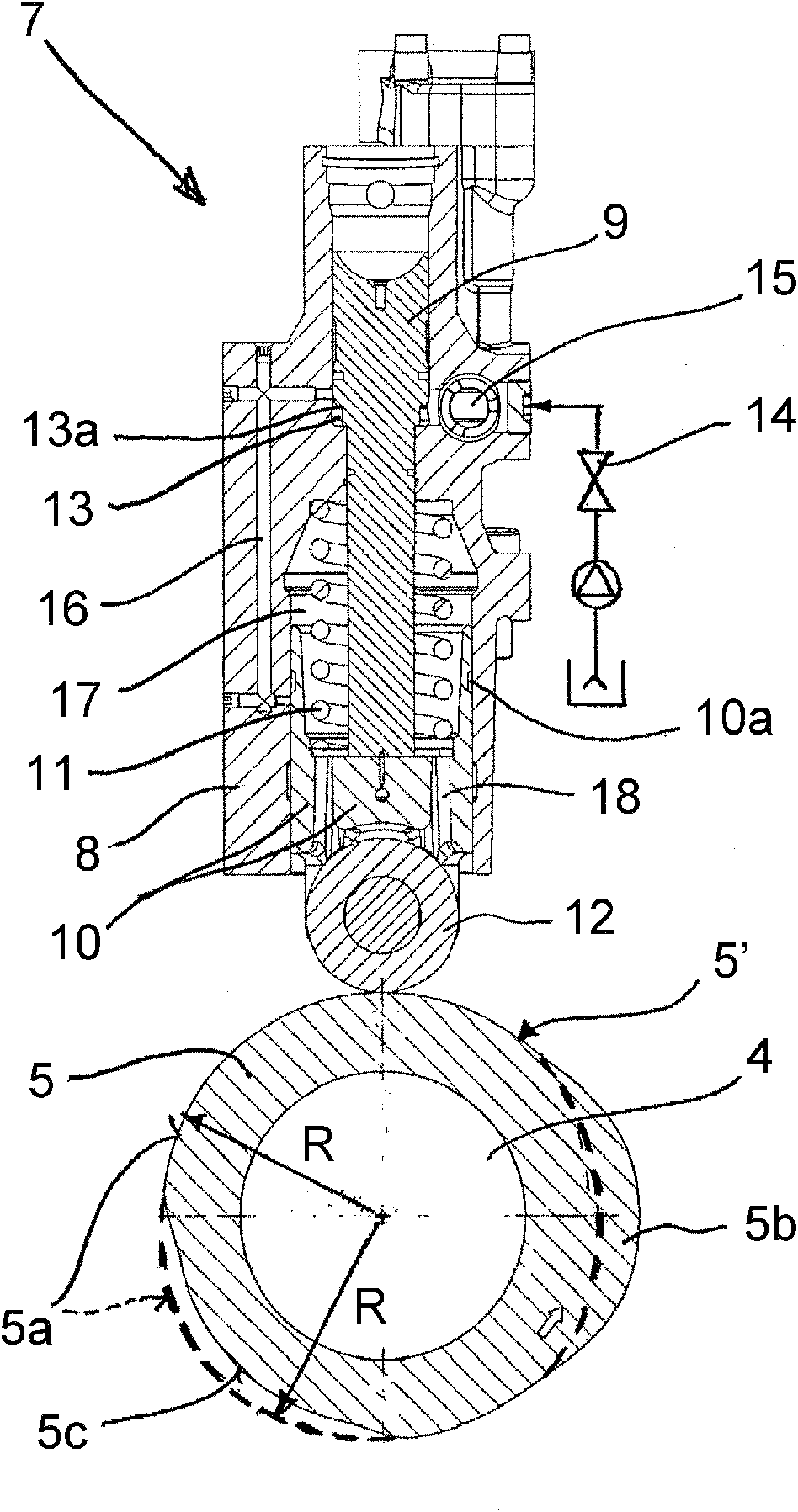
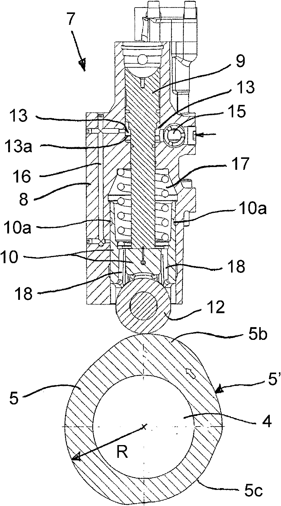
[0020] in Figure 2 to Figure 6 The control device 7 is shown in more detail in figure 2 The control device is shown in a non-operating state, whereby the intake valve 3 connected to it is closed. The control device 7 includes a body portion 8 that is usually attached to the engine body. The piston device 9 is movably arranged in the body ...


PUM


Abstract

The invention relates to a control arrangement for gas exchange in a piston engine adapted between a cam device (5) of a camshaft (4) of the engine (1) and an inlet valve mechanism (6) arranged to open and close the inlet valve (3) in association with a cylinder of the engine, which control arrangement (7) comprises a body part (8), in which a piston device (9) is movably arranged to be in force transmission connection with the camshaft (4) and the valve mechanism (6). The cam device (5) includes a cam profile (5') having a portion (5c) arranged under a base circle (5a) of the cam profile (5'). Said portion (5c) of the cam profile (5') is arranged to control gas exchange through the inlet valve (3), specifically for providing a delay in the closing of the inlet valve (3).

Description

Technical field [0001] The invention relates to a control device for gas exchange in a piston engine. Background technique [0002] There are situations in the operation of a four-stroke internal combustion engine in which the cylinder does not have enough air to self-ignite during the compression stroke. This is especially true for engines supercharged by high pressure, such as two-stage turbocharged engines, during engine start and during load changes. In this kind of engine, the higher pressure is combined with the sharper or shorter cam tip structure, which correspondingly leads to the boosting action in a shorter time. Therefore, the intake valve opening time under normal engine load is not long enough for this special case. [0003] On the other hand, in order to minimize the emissions of the diesel engine, the timing of the intake valve needs to be such that the intake valve closes before the bottom dead center of the piston, and at the same time, the boost pressure is cor...

Claims


Application Information

Patent Timeline
Patent Type & Authority Patents(China)
IPC IPC(8): F01L1/255F01L1/08F01L13/00F01L9/40
CPCF01L2013/0089F01L13/0031F01L2105/00F01L1/255F01L1/08F01L2305/00F01L9/11F01L13/00
Inventor 马格努斯·松德斯滕
Owner WARTSILA FINLAND OY
Why Eureka
Try Eureka