Panhandle rotating mechanism

A rotating mechanism and pot handle technology, which is applied to cooking utensils, household utensils, applications, etc., can solve the problems of unreliable connection, unfavorable transportation and storage, unfavorable manufacturing and installation, etc., so that it is not easy to loosen and shake, and the cost is low , the effect of simplifying the mechanism

Inactive Publication Date: 2011-07-06
胡志明
View PDF1 Cites 14 Cited by
  • Summary
  • Abstract
  • Description
  • Claims
  • Application Information

AI Technical Summary

Problems solved by technology

[0002] The traditional pot handle and pot body are connected and fixed, and generally cannot be rotated, resulting in a relatively large volume, which is not conducive to transportation and storage. For this reason, scientific and technological personnel have developed a new rotatable handle mechanism
[0003] Such as the Chinese patent "a rotatable pot handle" whose patent number is 200820168538.3, it includes a handle base, a handle arranged on the handle base, a button, a cross-sectional fixed pin and a spring, wherein the fixed pin head wears Through the handle and against the bottom of the button, there is an in-line block in the middle, and a slot matching the in-line block is opened on the bottom surface of the handle, and the tail of the fixe

Method used


Image

  • Panhandle rotating mechanism
  • Panhandle rotating mechanism
  • Panhandle rotating mechanism

Examples


Embodiment Construction

[0027] The present invention will be further described in detail below in conjunction with the accompanying drawings and embodiments.

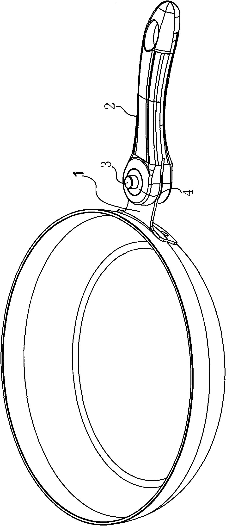
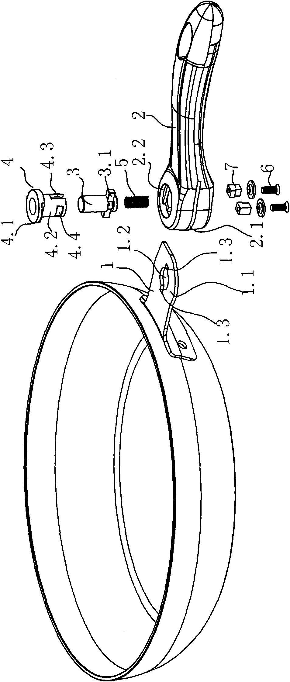
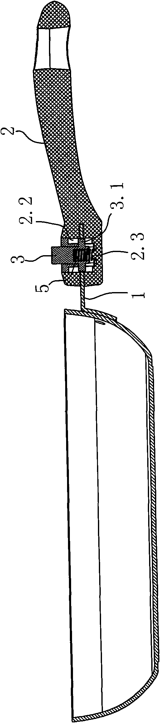
[0028] like Figure 1-2 As shown, a pot handle rotation mechanism includes main components such as a handle base 1, a handle 2, a button 3, a positioning sleeve 4, a spring 5, a screw 6, and a block 7;

[0029] Among them, the handle base 1 is made of bent metal plate, showing a general L shape, and the inner connection end adopts an arc shape that matches the shape of the pot body, so that it fits the pot body, and is connected and fixed with the pot body by means of rivets or welding. , the other end of the shank 1 adopts a flat connecting part 1.1, and the connecting part has a central hole 1.2, and the left and right sides of the central hole (based on the position on the drawing) are respectively symmetrically opened with a limit opening 1.3, and the limit opening 1.3 can be It may or may not be connected to the central hole 1.2;

[003...


PUM


Abstract

The invention relates to a panhandle rotating mechanism which comprises a handle seat, a handle, a button and a spring, wherein the connecting end of the handle seat is connected with a pan body, and the other end of the handle seat is connected with the handle; the inner end of the handle is connected with the handle seat, and a cavity is arranged at a position close to the inner end of the handle; the button is arranged in the cavity; and the spring enables the button to be keep a trend of always moving towards the surface of the handle. The panhandle rotating mechanism is characterized in that: a flat connecting part is arranged at the other end of the handle seat, and the connecting part is provided with a central hole with a limit port; correspondingly, a slot in which the connecting part of the handle seat is inserted and rotated is arranged at the inner end of the handle; the button is provided with a locking block in an downward extending way, and the locking block is in locked or unlocked matching with the limit port; and the panhandle rotating mechanism further comprises a positioning sleeve which is fixed at the mouth part of the cavity so that the surface of the button exposes outside the positioning sleeve and the button is limited from ejecting out of the installation cavity. The invention has the advantages of more compact and reasonable structure, connection stability and long service life.

Description

technical field [0001] The invention relates to a pan handle rotating mechanism. Background technique [0002] The traditional pot handle and pot body are connected and fixed, and generally cannot be rotated, resulting in a relatively large volume, which is not conducive to transportation and storage. For this reason, scientific and technological personnel have developed a new rotatable handle mechanism. [0003] Such as the Chinese patent "a rotatable pot handle" whose patent number is 200820168538.3, it includes a handle base, a handle arranged on the handle base, a button, a cross-sectional fixed pin and a spring, wherein the fixed pin head wears Through the handle and against the bottom of the button, there is an in-line block in the middle, and a slot matching the in-line block is opened on the bottom surface of the handle, and the tail of the fixed pin has a flat stopper. The tail of the fixed pin is inserted into the handle seat, and the spring makes the fixed pin ha...

Claims


Application Information

Patent Timeline
IPC IPC(8): A47J36/00
Inventor 罗欣胡志明
Owner 胡志明
Why Eureka
Try Eureka