Method and system for preventing error locking of DLL (Delay-Locked Loop)

A delay-locked loop and error technology, which is applied in the field of delay-locked loops, can solve problems such as delay-locked loop error locking, control logic circuit error sending out locking signals, etc., to speed up the locking process, control logic is simple, and compatibility is good Effect

Active Publication Date: 2011-08-10
XI AN UNIIC SEMICON CO LTD
View PDF6 Cites 16 Cited by
  • Summary
  • Abstract
  • Description
  • Claims
  • Application Information

AI Technical Summary

Problems solved by technology

[0015] However, see image 3 , when the above-mentioned locking process of the delay-locked loop is adopted, when the falling edge of the feedback clock is sampled, if the sampling output signal is 1, when the input clock or the feedback clock has jitter, the sampling output signal becomes 0, and the control logic The circuit will erroneously send out the lock signal, which will cause the delay-locked loop to lock on the falling edge incorrectly (such as image 3 in the circle)

Method used


Image

  • Method and system for preventing error locking of DLL (Delay-Locked Loop)
  • Method and system for preventing error locking of DLL (Delay-Locked Loop)
  • Method and system for preventing error locking of DLL (Delay-Locked Loop)

Examples


Embodiment Construction

[0042] The invention divides the frequency of the input clock input to the phase detector and the feedback clock, and locks the frequency division signal. The specific process is as follows:

[0043] see Figure 4-6 , (1) The delay continues to increase:

[0044] (1.1) After the input clock is frequency-divided by the input clock frequency division circuit, the obtained frequency-division input clock is respectively input to the I phase detector and II phase detector of the control logic circuit;

[0045] (1.2) After the feedback clock is differentially divided by the feedback clock frequency division circuit, two differential feedback clocks are obtained. One differential feedback clock is the frequency division feedback clock, which is input to the I phase detector of the control logic circuit, and the other is frequency division. The feedback clock is input to the II phase detector of the control logic circuit;

[0046] (1.3) I phase detector and II phase detector sample...


PUM


Abstract

The invention provides a method and system for preventing the error locking of a DLL (Delay-Locked Loop). The method comprises the following steps: (1) a continuous delay increasing step; and (2) a trimming step, wherein the step (1) concretely comprising the following steps of : (1.1) dividing the frequency of an input clock by an input clock frequency dividing circuit and respectively inputtingthe acquired divided-frequency input clocks into a phase discriminator (I) and a phase discriminator (II) of a control logical circuit; ( 1.2) differentially dividing the frequency of a feedback clock by a feedback clock frequency dividing circuit to acquire two paths of differential feedback clocks and respectively inputting the two paths of differential feedback clocks into the phase discriminator (I) and the phase discriminator (II) of the control logical circuit; and (1.3) sampling and comparing the divided-frequency input clock and the two paths of differential feedback clocks by the phase discriminator (I) and the phase discriminator (II) and emitting a locking signal when the outputs of the phase discriminator (I) and the phase discriminator (II) jump from 1 to 0 or from 0 to 1. The method and system provided by the invention can effectively prevent the error locking phenomenon of the DLL in case of the jitter of the input clock, are simple in control logic and can accelerate the locking process.

Description

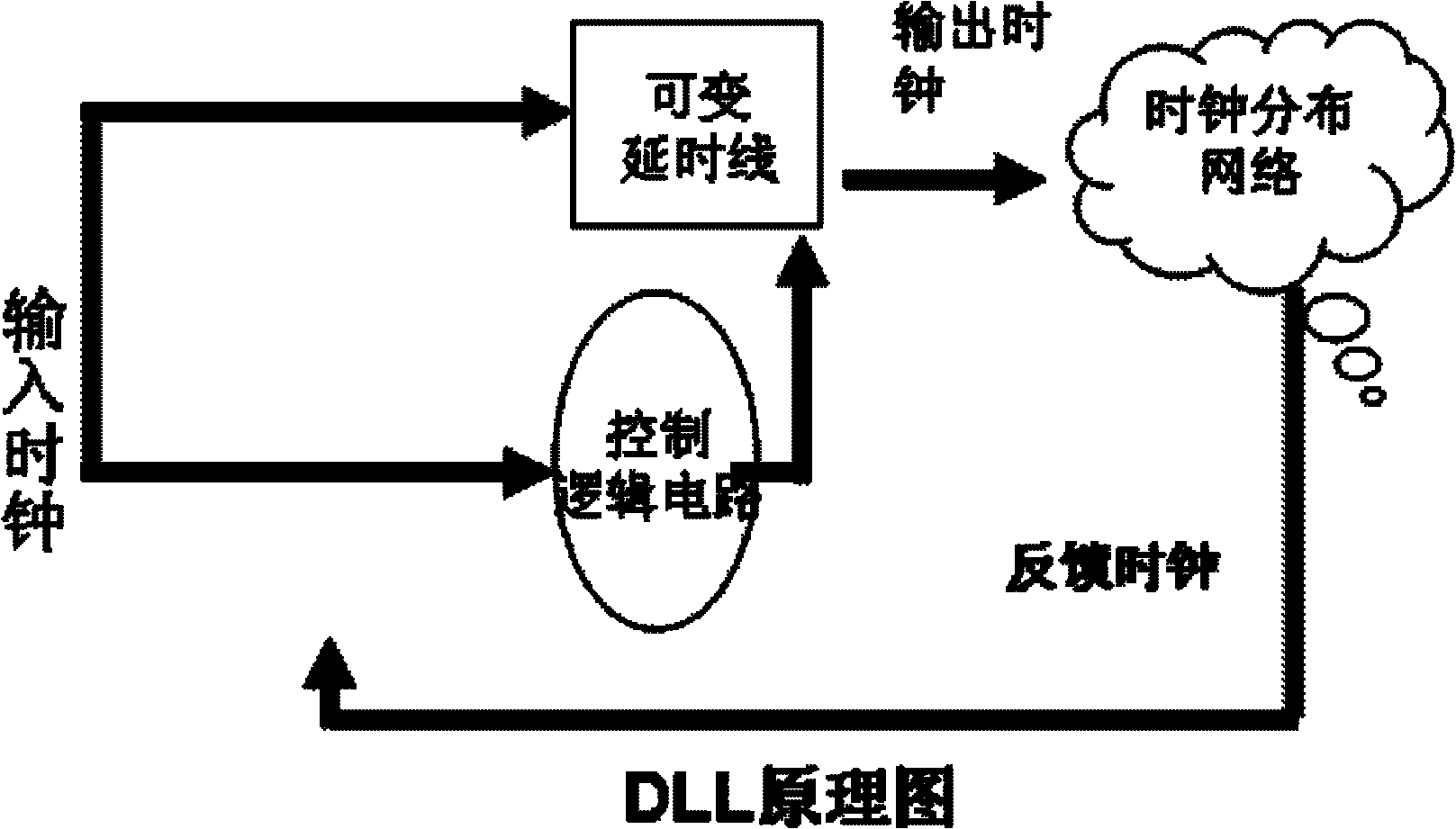
technical field [0001] The invention belongs to the field of delay-locked loops, in particular to a method and system for preventing wrong locking of delay-locked loops. Background technique [0002] A delay-locked loop is a delay-output system that generates an input clock through a delay line. [0003] see figure 1 , the specific basic working principle of the delay-locked loop is as follows: [0004] Step 1: The output clock of the delay-locked loop passes through the clock distribution network to generate a feedback clock, and the feedback clock is re-input into the delay-locked loop. [0005] Step 2: The phase detector of the delay-locked loop samples and compares the input clock and the feedback clock, and outputs the comparison result to the control logic circuit, [0006] Step 3: The control logic circuit adjusts the delay of the variable delay line according to the comparison result, so as to realize zero transmission delay between the feedback clock and the inpu...

Claims


Application Information

Patent Timeline
IPC IPC(8): H03L7/08
CPCH03L7/08H03L7/0816H03L7/10H03L2207/14
Inventor亚历山大刘天志
OwnerXI AN UNIIC SEMICON CO LTD