Electrodeless illuminating lamp

A technology for lighting lamps and light-emitting tubes, which is applied in the field of lighting lamps, can solve the problems that the heat of lamps cannot be dissipated well, there is no cooling and cooling device, and the service life is affected, and the effects of simple structure, prolonged service life and high light efficiency are achieved.

Active Publication Date: 2011-11-16
杨卡
View PDF4 Cites 2 Cited by
  • Summary
  • Abstract
  • Description
  • Claims
  • Application Information

AI Technical Summary

Problems solved by technology

But it does not have a cooling device, the heat generated by the lamp cannot be dissipated well, which affects its service life

Method used


Image

  • Electrodeless illuminating lamp
  • Electrodeless illuminating lamp
  • Electrodeless illuminating lamp

Examples


Embodiment 1

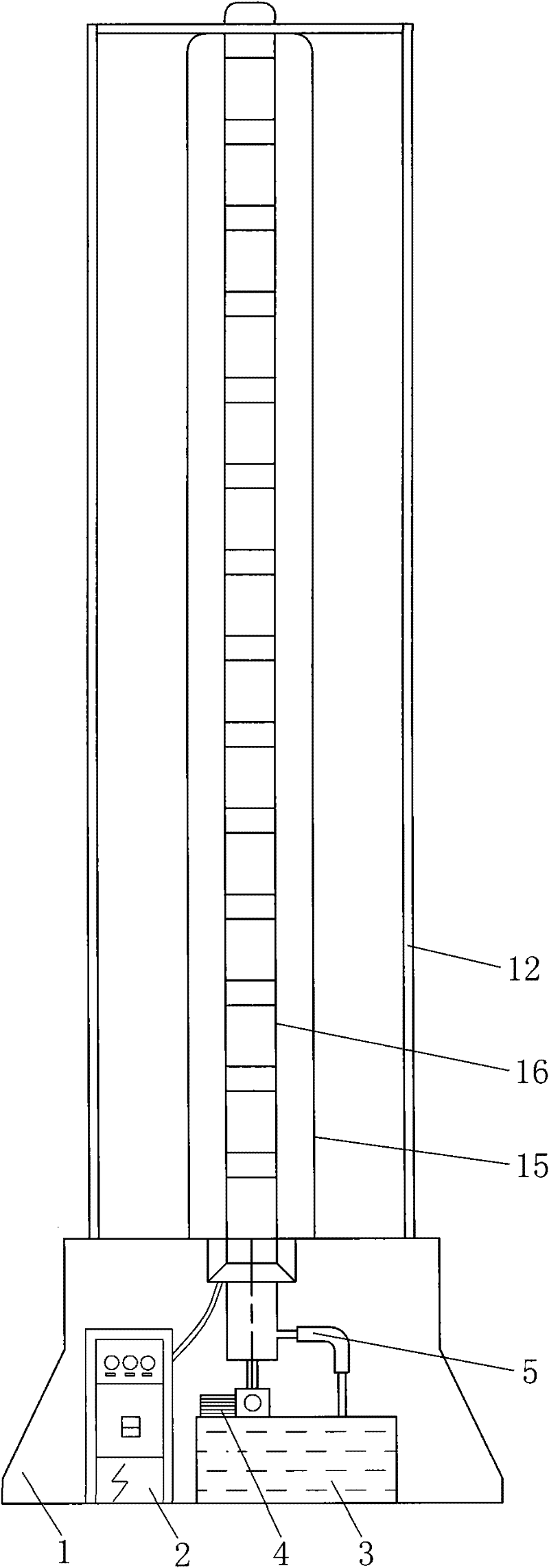
[0017] Embodiment 1: as figure 1 As shown, the present invention includes a base 1 with a built-in electric control cabinet 2 and a cooling system, a bracket 12, a luminous tube 15 and a coupler 16, the bracket 12 is placed on the base 1, and the luminous tube 15 is installed on the base 1 in the bracket 12. And respectively connected with the electric control cabinet 2 and the cooling system, the coupler 16 is placed in the luminous tube 15, and the positive and negative poles of the coil 13 are respectively connected with the electric control cabinet 2.

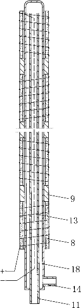
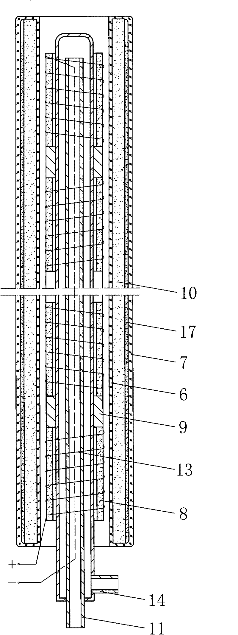
[0018] Such as figure 2 As shown, the coupler 16 of the present invention includes an inner water pipe 11, an outer water pipe 18, a coil 13, multiple sets of magnets 8 and magnetic isolation sleeves 9, wherein the number of sets of magnets 8 is determined according to user needs, and four are selected in this example , the magnets 8 separated by magnetic isolation sleeves 9 are set on the outer water pipe 18, the coil 13...

Embodiment 2

[0022] Embodiment 2: The overall structure of this example is the same as that of Embodiment 1, but the difference is that there are 10 magnets 8 in the coupler 16 of this example, and the winding method of its coil 13 and the installation method of the magnets 8 are the same as those of Embodiment 1, namely: The magnetic poles of the two adjacent magnets 8 are the same, and the winding methods of the coils 13 are opposite. Wherein the inner water pipe 11, the outer water pipe 18 are connected to the cooling system as follows: the water nozzle 14 of the outer water pipe 18 is connected to the water outlet of the water pump 4 through the water pipe, and the inner water pipe 11 is connected to the water tank 3, then the water circulation is: in the water tank 3 The water enters the outer water pipe 18 through the water pump 4, flows out to the water tank through the inner water pipe 11, and completes the water cooling cycle.

Embodiment 3

[0023] Embodiment 3: The overall structure of this example is the same as that of Embodiment 1, but the difference is that there are 14 magnets 8 in the coupler 16 of this example, and the winding method of its coil 13 and the installation method of the magnets 8 are the same as those of Embodiment 1, that is: The magnetic poles of the two adjacent magnets 8 are the same, and the winding methods of the coils 13 are opposite.


PUM


Abstract

An electrodeless illuminating lamp, which belongs to the illuminating lamp technology field, is disclosed. The electrodeless illuminating lamp comprises: an electric control cabinet, a pedestal, a support, a luminous tube, a coupler and a cooling system. The support is placed on the pedestal. The tube is installed on the pedestal in the support. The coupler is arranged in the luminous tube. The cooling system is used to cool the coupler. The coupler is respectively connected with the electric control cabinet and the cooling system. The coupler comprises: an inner water pipe, an external water pipe, a coil, multi-group magnets and a magnetic shield. The magnets are sleeved on the external water pipe, wherein the magnetic shield is arranged between the magnets. The coil is wound around the magnets. Coil winding directions of two adjacent magnets are opposite and magnetic poles of opposite ends of the adjacent magnets are same. Two ends of the coil form an anode and a cathode which are respectively connected with the electric control cabinet. The inner water pipe is arranged in the external water pipe, extends out of the external water pipe and forms seal connection with the end of the external water pipe. The inner water pipe is connected with a water pump of the cooling system and a water outlet nozzle is arranged on the external water pipe. In the invention, arbitrary multi-group magnets are adopted to form different models of the electrodeless illuminating lamps. A large or an ultra-large illuminating lamp can be made.

Description

technical field [0001] The invention relates to an illuminating lamp, which belongs to the technical field of illuminating lamps. It is a large electrodeless lighting suitable for squares, ports, supermarkets, department stores, stadiums and other public places. technical background [0002] Most of the existing lighting lamps are small lighting fixtures with a small lighting range. When used in large places such as squares, multiple lighting fixtures need to be added for combined use. The patent number is "200710037004.7", a combined seamless soft light large-scale decorative lighting fixture, which is mainly composed of a light source, a lamp body, a reflector and a light-transmitting layer. The light source is placed on the reflector, and the reflector and light-transmitting layer Layers are placed on both sides of the light source, and the lamp body is composed of combinable profiles connected through connectors, and then combined into lamps of different sizes. It uses...

Claims


Application Information

Patent Timeline
Patent Type & Authority Applications(China)
IPC IPC(8): H01J65/00H01J61/52
Inventor 许树良
Owner 杨卡
Why Eureka
Try Eureka