Straight wing hydroelectric power generation device

A technology of hydroelectric power generation and straight wings, which is applied in the directions of hydropower generation, renewable energy power generation, engine components, etc., can solve the problems of unsuitability of water turbines, and achieve good application value, high hydraulic conversion efficiency, and improved efficiency.

Inactive Publication Date: 2011-11-30
ZHEJIANG FENGSHEN MARINE ENG TECH
View PDF6 Cites 5 Cited by
  • Summary
  • Abstract
  • Description
  • Claims
  • Application Information

AI Technical Summary

Problems solved by technology

The above-mentioned water turbines are not suitable for working in flowing water flow with small pressure head

Method used


Image

  • Straight wing hydroelectric power generation device
  • Straight wing hydroelectric power generation device
  • Straight wing hydroelectric power generation device

Examples


Embodiment 1

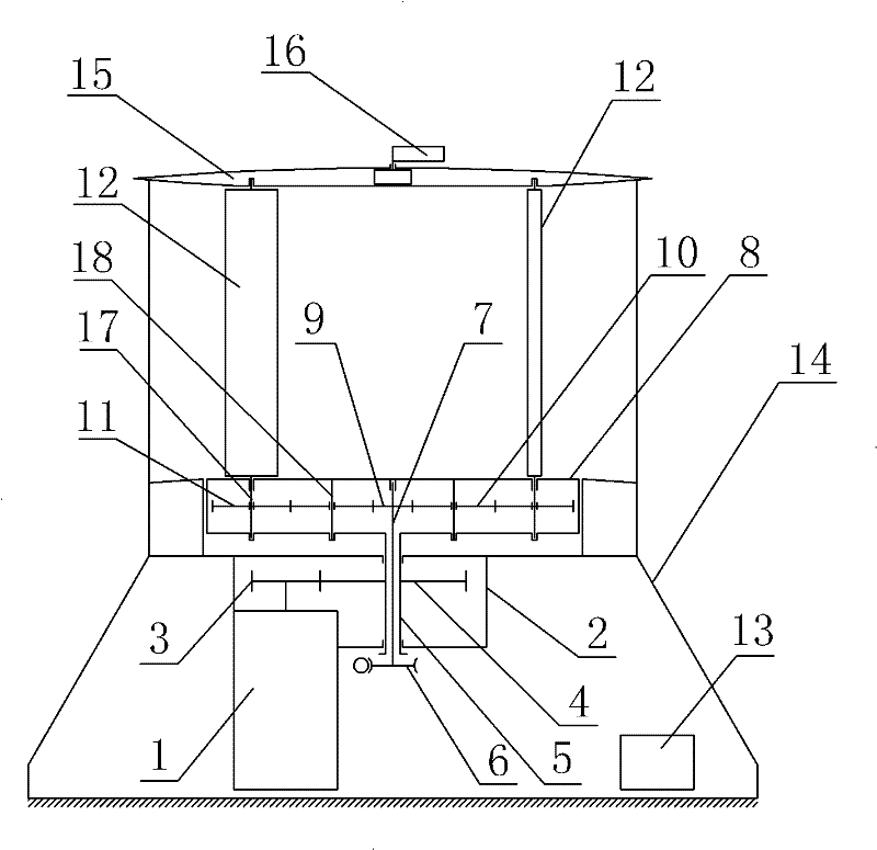
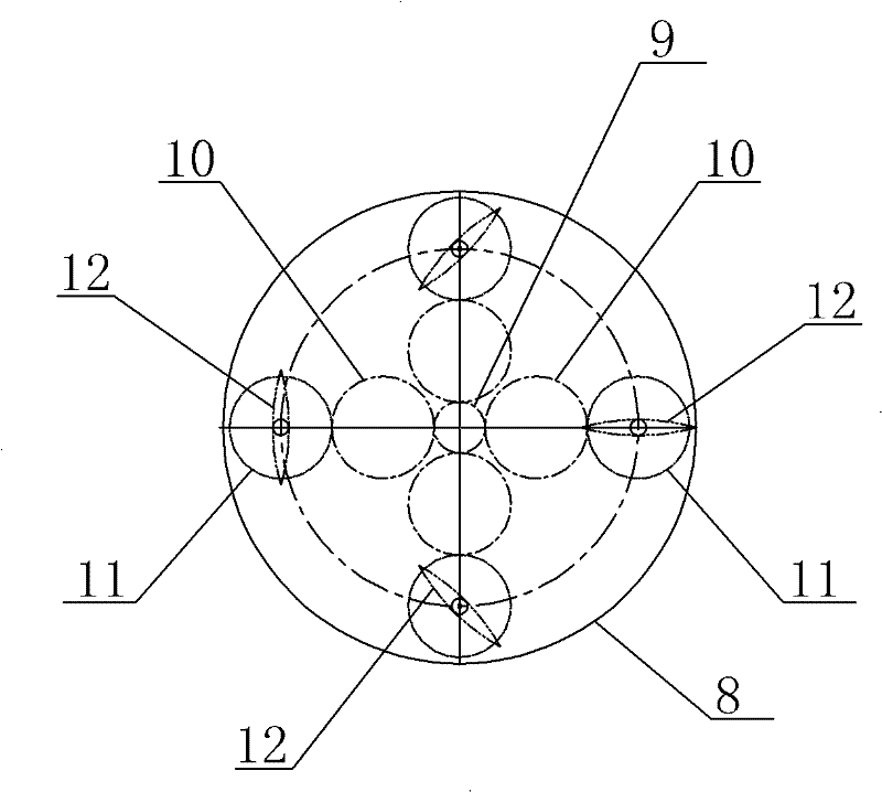
[0025] Embodiment one: if Figure 1-3 As shown, the straight-wing hydroelectric power generation device of this embodiment includes a generator 1, a gearbox 2, a generator gear 3, a main gear 4, a main shaft 5, a water flow orientation controller 6, a transmission shaft 7, a rotating disc 8, and a central gear 9 , bridge gear 10, paddle gear 11, paddle 12, base 14, guide plate 15, water flow sensor 16, paddle shaft 17, the longitudinal section of base 14 is isosceles trapezoidal shape, and it forms accommodation area , a generator 1 and a gear box 2 are built into the accommodation area, the shaft of the generator 1 extends into the gear box 2, and is fixedly connected with the middle part of the gear 3 in the gear box 2, the gear 3 meshes with the main gear 4, and the main gear 4 is also in the gearbox 2. The middle part of the main gear 4 passes through the main shaft 5, and the two are fixedly connected. The lower end of the main gear 5 and the lower wall of the gear box 2...

Embodiment 2

[0031] Embodiment two: see Figure 4 , using a direct-drive generator 1, the generator seat 2 is fixed on the upper bottom of the base 14, and its shaft is directly connected to the main shaft 5 and directly driven by the main shaft 5, thereby saving the transmission mechanism and further simplifying the structure of the generator. For other content of this embodiment, refer to Embodiment 1.

Embodiment 3

[0032] Embodiment three: see Figure 5 , The transmission part of this embodiment adopts a toothed belt or a chain 19, and the central gear 9 is connected with the paddle gear 11 through a toothed belt or a chain 19. For other content of this embodiment, refer to Embodiment 1 or Embodiment 2.


PUM


Abstract

The invention relates to a straight-wing water flow power generation device. The gear box is fixed in the base, and the rotating disk is arranged above the base. ; The main shaft is linked with the shaft of the generator, the main shaft and the gear box rotate in cooperation, the upper end of the main shaft passes through the upper wall of the gear box and is fixedly connected with the rotating disk; Out of the main shaft and the gear box, it is connected with the water flow direction controller. The upper end passes through the lower wall of the rotating disk to move with the central gear in the rotating disk. This end is in rotation with the upper wall of the rotating disk; Several paddle gears are evenly distributed on the paddle shaft, and the paddle gear is connected with the central gear through a transmission member; the paddle shaft protrudes from the upper wall of the rotating disk, and is fixedly connected to one end of the paddle, and the other end of the paddle rotates to match On the deflector plate; the rotating plate rotates once, and the blade rotates half a circle around its own axis. The present invention can be suitable for running at high and low speeds.

Description

technical field [0001] The invention belongs to the technical field of water flow power generation devices, in particular to a straight wing water flow power generation device. Background technique [0002] At present, hydropower generation mainly uses the water level drop to convert the rotation of the water turbine to drive the generator to generate electricity. There are two main forms of more mature hydropower generation: storage power generation with high water head and tidal power generation with low water head. Water storage power generation requires supporting projects such as blocking the river, repairing dams and building ship locks, and tidal power generation requires large-scale engineering transformation of the bay. Therefore, the current hydropower facilities require huge investment, high maintenance costs, and have a significant impact on the environment. The main types of existing water turbines are: impact water turbine and impact water turbine, impact wate...

Claims


Application Information

Patent Timeline
Patent Type & Authority Applications(China)
IPC IPC(8): F03B13/00F03B3/12F03B3/18F03B11/00
CPCY02E10/223Y02E10/226Y02E10/20
Inventor 黄佳林
Owner ZHEJIANG FENGSHEN MARINE ENG TECH
Why Eureka
Try Eureka