Suction surface sucking stator blade of air compressor

A technology of stator blades and suction surfaces, which is applied in mechanical equipment, machines/engines, liquid fuel engines, etc., can solve the problems of high power and cost of suction equipment, and achieve the effect of effective suction and saving test costs.

Inactive Publication Date: 2013-04-24
NORTHWESTERN POLYTECHNICAL UNIV
View PDF3 Cites 0 Cited by
  • Summary
  • Abstract
  • Description
  • Claims
  • Application Information

AI Technical Summary

Problems solved by technology

[0006] In order to overcome the problem of pumping air through a single suction hole in the prior art, it is necessary to process multiple sets of adsorption compressor blades / cascades, conduct multiple sets of adsorption compressor tests, and install the adsorption compressor on each stator blade. slotting, the power of the required suction equipment is relatively large, and it consumes more funds. The present invention proposes a compressor stator vane with suction surface suction.

Method used


Image

  • Suction surface sucking stator blade of air compressor
  • Suction surface sucking stator blade of air compressor
  • Suction surface sucking stator blade of air compressor

Examples


Embodiment 1

[0024] This embodiment is a compressor stator blade with suction surface suction, which is used for boundary layer suction and testing on the 0-50% span area of ​​the suction surface of the compressor stator blade.

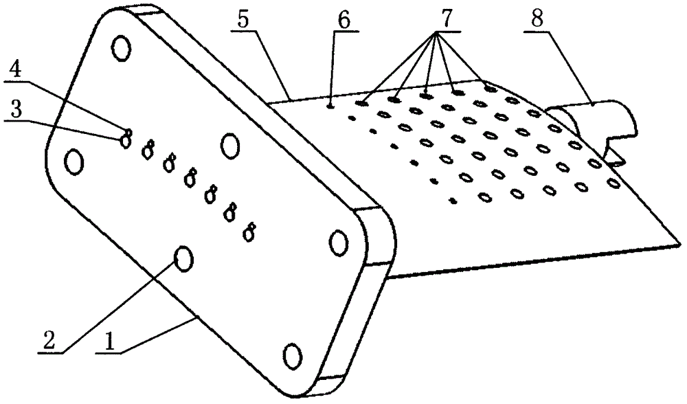
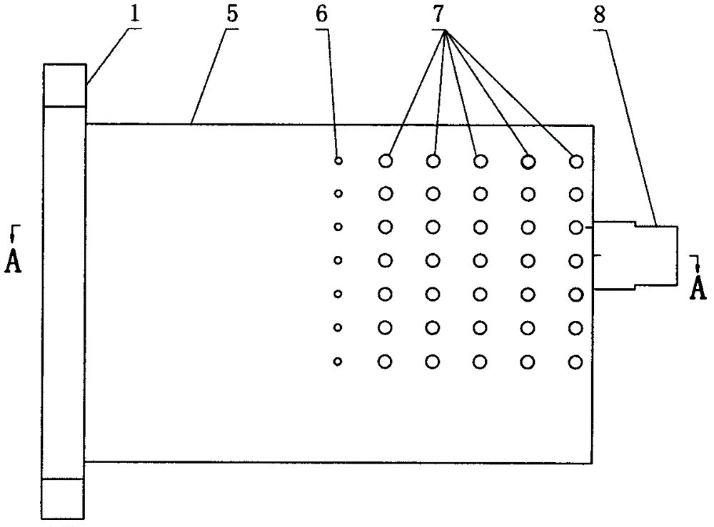
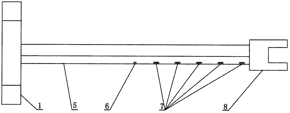
[0025] Such as figure 1 As shown, a stator blade of a suction side suction compressor proposed in this embodiment includes a blade body 5 and a blade shroud 1 . There is a fixed pin 8 at the blade tip. There are 35 suction holes 7 and 7 static pressure holes 6 distributed on the suction surface of the blade body 5 .

[0026] The suction holes 7 are divided into 7 rows, uniformly arranged from the leading edge to the trailing edge of the blade body 5, and the distance between the center of the first row of suction holes 7 and the leading edge of the blade is 12% of the chord length, the seventh The distance between the center of the row of suction holes 7 and the trailing edge of the blade is 28% of the chord length; the distance between the first row of suction ...

Embodiment 2

[0035] This embodiment is a compressor stator blade with suction surface suction, which is used to perform boundary layer suction and test on the 45-100% blade span area of ​​the suction surface of the compressor stator blade.

[0036] Such as figure 1 As shown, a stator blade of a suction side suction compressor proposed in this embodiment includes a blade body 5 and a blade shroud 1 . There is a fixed pin 8 at the blade tip. There are 25 suction holes 7 and 5 static pressure holes 6 distributed on the suction surface of the blade body 5 .

[0037] The suction holes 7 are divided into 5 rows, which are uniformly arranged from the leading edge to the trailing edge of the blade body 5, and the distance between the center of the first row of suction holes 7 and the leading edge of the blade is 50% of the chord length, the fifth The distance between the center of the row of suction holes 7 and the trailing edge of the blade is 10% of the chord length; the distance between the f...

Embodiment 3

[0046] This embodiment is a compressor stator blade with suction surface suction, which is used to perform boundary layer suction and test on the 20-80% span area of ​​the suction surface of the compressor stator blade.

[0047] Such as figure 1 As shown, a stator blade of a suction side suction compressor proposed in this embodiment includes a blade body 5 and a blade shroud 1 . There is a fixed pin 8 at the blade tip. There are 90 suction holes 7 and 9 static pressure holes 6 distributed on the suction surface of the blade body 5 .

[0048] The suction holes 7 are divided into 9 rows, 10 in each row, evenly arranged from the leading edge to the trailing edge of the blade body 5, and the distance between the center of the first row of suction holes 7 and the leading edge of the blade is 10%. Chord length, the distance between the center of the ninth row of suction holes 7 and the trailing edge of the blade is 15% of the chord length; the distance between the first row of su...


PUM


Abstract

The invention discloses a suction surface sucking stator blade of an air compressor. A plurality of suction holes and a plurality of static vents are distributed at the suction surface of a blade body. The suction holes are uniformly arranged between the front edge and the rear edge of the blade body. The number of the static vents is the same as the rows of the suction holes. The static vents are distributed into one row from the front edge to the rear edge of the blade body, and are positioned between the suction holes and blade roots or blade tips. Vacuum cavities and static pressure cavities which are communicated with a blade head are arranged in the blade body. The number of the vacuum cavities is the same as the rows of the suction holes, and the number of the static pressure cavities is as the same as that of the static vents. All the vacuum cavities in the blade body are communicated with the blade head, and the suction air on the blade body surface is discharged through the blade head after entering the vacuum cavities; and all the static pressure cavities in the blade body are communicated with the blade head, so the static vents are communicated with the static pressure cavities in the blade body, the static pressure is transferred to the outer side of the air compressor through the blade head, the static pressure variation on the blade surface before and after thesuction can be measured through the static vents, so the influence of the suction of the boundary layer of the blade surface on the performance of the air compressor is determined.

Description

technical field [0001] The invention relates to an adsorption type stator vane which adopts the layout of local suction holes to improve the aerodynamic performance of a compressor, in particular to a compressor stator vane with suction surface suction. Background technique [0002] The development of modern high-performance aero-engines requires higher pressure ratio and efficiency of its key components, the compressor. Increasing the bending angle of the compressor cascade to increase the turning angle of the airflow in the compressor cascade is one of the methods to increase the pressure ratio and load of the compressor, but increasing the bending angle is often accompanied by boundary layer separation, which makes the compressor efficiency and circulation capacity has dropped significantly. [0003] In 1997, Professor Kerrebrock proposed the concept of an adsorption compressor for the first time, pointing out that suction through the boundary layer on the blade surface ...

Claims


Application Information

Patent Timeline
Patent Type & Authority Patents(China)
IPC IPC(8): F04D29/38
Inventor 刘波曹志远赵鹏程高丽敏楚武利
Owner NORTHWESTERN POLYTECHNICAL UNIV
Why Eureka
Try Eureka