Device for electrical connection and circuit breaker

A technology for electrical connection devices and circuit breakers, applied in the direction of circuits, electrical components, protective switch terminals/connections, etc.

Active Publication Date: 2015-04-15
SCHNEIDER ELECTRIC IND SAS
View PDF3 Cites 0 Cited by
  • Summary
  • Abstract
  • Description
  • Claims
  • Application Information

AI Technical Summary

Problems solved by technology

This shaping of the strip into the housing is restricted and requires the use of special tools

Method used


Image

  • Device for electrical connection and circuit breaker
  • Device for electrical connection and circuit breaker
  • Device for electrical connection and circuit breaker

Examples


Embodiment Construction

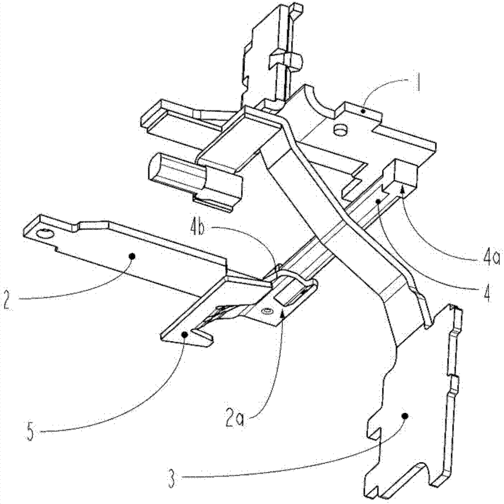
[0017] exist figure 1 In , there can be seen a contact strip 1 belonging to a circuit breaker in a known manner, a bimetallic strip 2 and an angle arrester 3, the bimetal strip 2 representing the thermal tripping device of the circuit breaker, enabling the circuit breaker contacts to Opens on electrical overload. The bimetal strip 2 and the contact strip 1 are electrically connected by a braid 4 which is fixed via its one end 4a to the contact strip 1 and via its opposite end 4b to the supporting bimetal strip The support member 5 of the foot 2a.

[0018] exist figure 1 , the strip is in the installed position prior to assembly. The strip does not have any memory shape. Before assembling the assembly in the circuit breaker housing, first the bimetallic strip 2 must be manually arranged on the correct side of the contact strip 1 and then inserted into its receptacle. The bimetallic strip must then be inserted into its housing in order to finally compact the strip in its ho...


PUM


Abstract

The device has a flat conducting part (6) fixed on a terminal pad (1) and a bimetal (2), where the part is formed from copper band. The part is formed by a conductor element continuously wound and flattened so as to provide length corresponding to a gap between a foot (2a) of bimetal and the terminal pad and a semi-rigid structure. The structure permits the deformation of the part under handling effect of an adjusting screw (7) so as to permit the displacement of bimetal while being sufficiently rigid for assuring relative positioning of the foot with respect to a contact pad.

Description

technical field [0001] The invention relates to an electrical connection device for electrically connecting the legs of a bimetallic strip to a contact strip in an electrical switching device, said bimetallic strip being movable by means of an adjusting screw for thermal regulation of the bimetallic strip. Background technique [0002] Connecting devices comprising woven braids for the electrical connection between the legs of the bimetallic strip and the contact strips in circuit breakers are known. However, these bands are bulky. Furthermore, the elements connected by the strip, ie the bimetallic strip and the contact strip, must be installed respectively in the circuit breaker before the strip is fitted in its housing, said strip having to be shaped so as not to memorize its shape. This shaping of the strip into the receptacle is restricted and requires the use of special tools. Contents of the invention [0003] The present invention solves these problems and propose...

Claims


Application Information

Patent Timeline
Patent Type & Authority Patents(China)
IPC IPC(8): H01H71/08
CPCH01H71/08H01H71/7436H01H71/16
Inventor M.伯里亚尔
Owner SCHNEIDER ELECTRIC IND SAS
Why Eureka
Try Eureka