Self-propelled compensating return stroke sweeper for conveying belt

A technology for conveyor belts and cleaners, which is applied in the direction of conveyor objects, cleaning devices, transportation and packaging, etc. It can solve the problems of cleaning rubber without automatic compensation, limit state cannot be predicted in time, and the flexibility adjustment of the surface of the conveyor belt is not flexible enough. , to achieve the effects of enhanced reliability, small footprint, and low maintenance costs

Active Publication Date: 2012-02-01
BAOSHAN IRON & STEEL CO LTD
View PDF4 Cites 5 Cited by
  • Summary
  • Abstract
  • Description
  • Claims
  • Application Information

AI Technical Summary

Problems solved by technology

[0004] 1. There is no automatic compensation for cleaning the rubber;
[0005] 2. The cleaning rubber is not flexible enough to adjust the elasticity of the "fluctuating" conveyor belt surface;
[0006] 3. The limit state of the cleaning rubber in the prior art cannot be predicted in time, and manual cycle inspection and monitoring are required

Method used


Image

  • Self-propelled compensating return stroke sweeper for conveying belt
  • Self-propelled compensating return stroke sweeper for conveying belt
  • Self-propelled compensating return stroke sweeper for conveying belt

Examples


Embodiment Construction

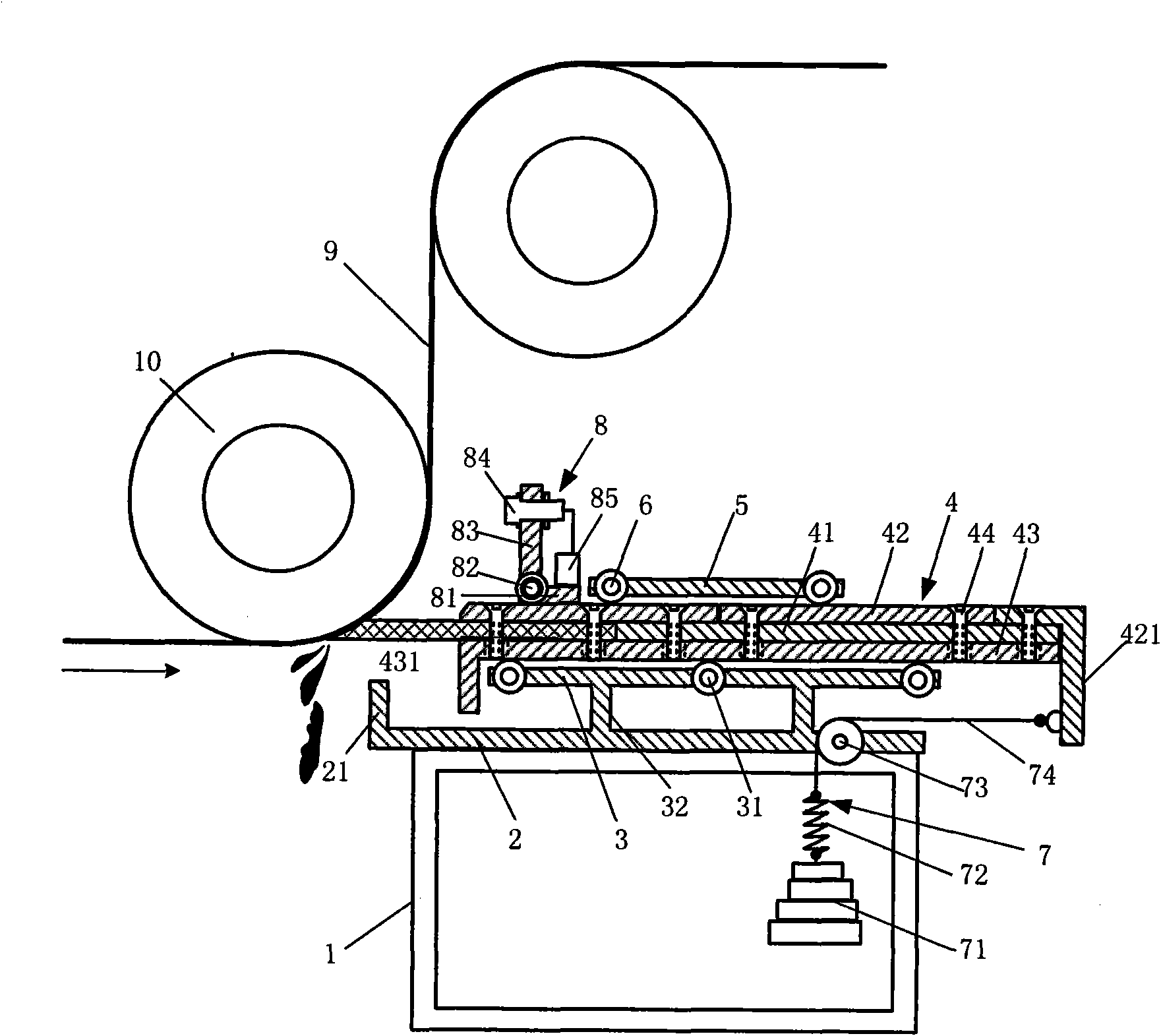
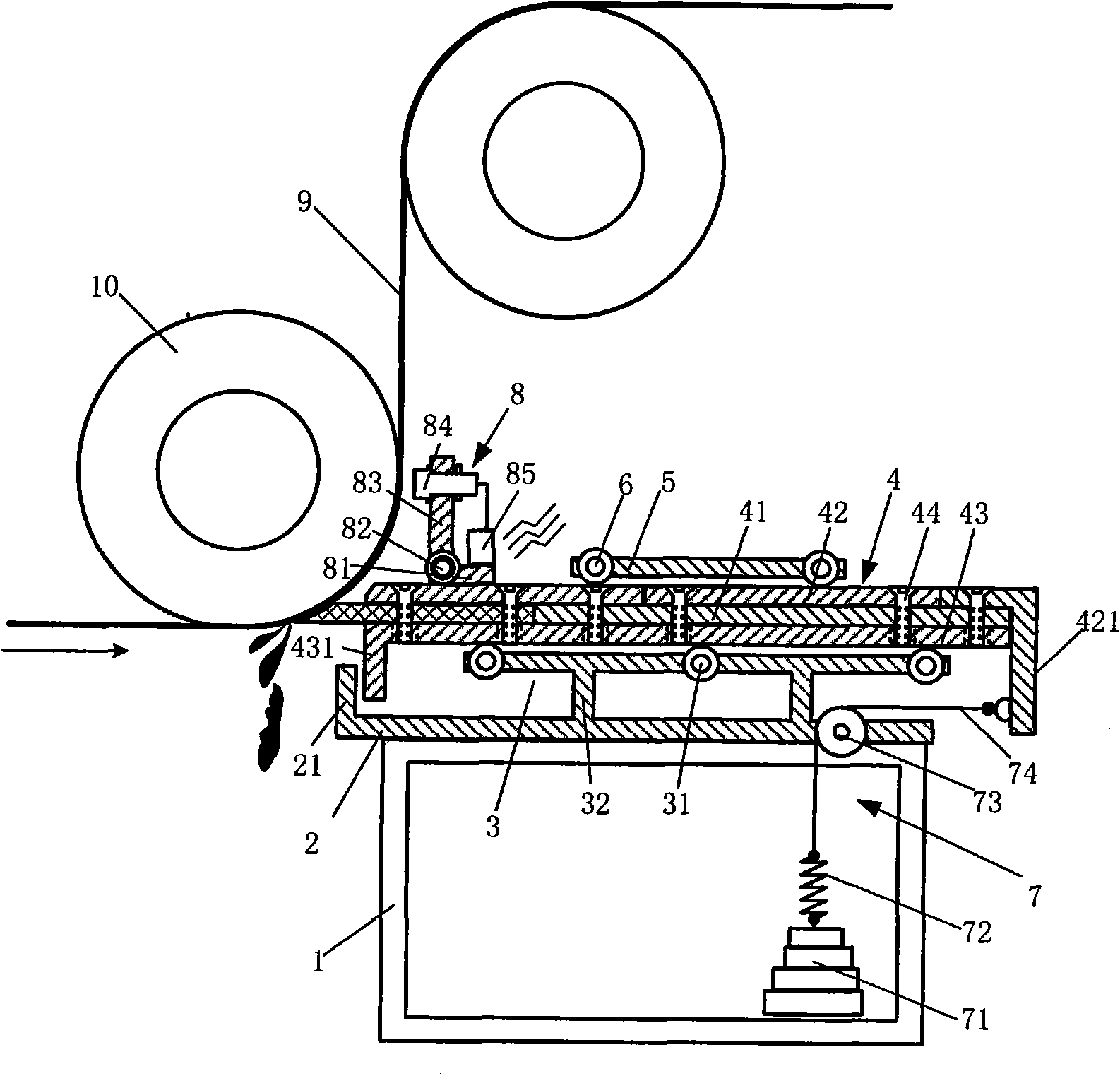
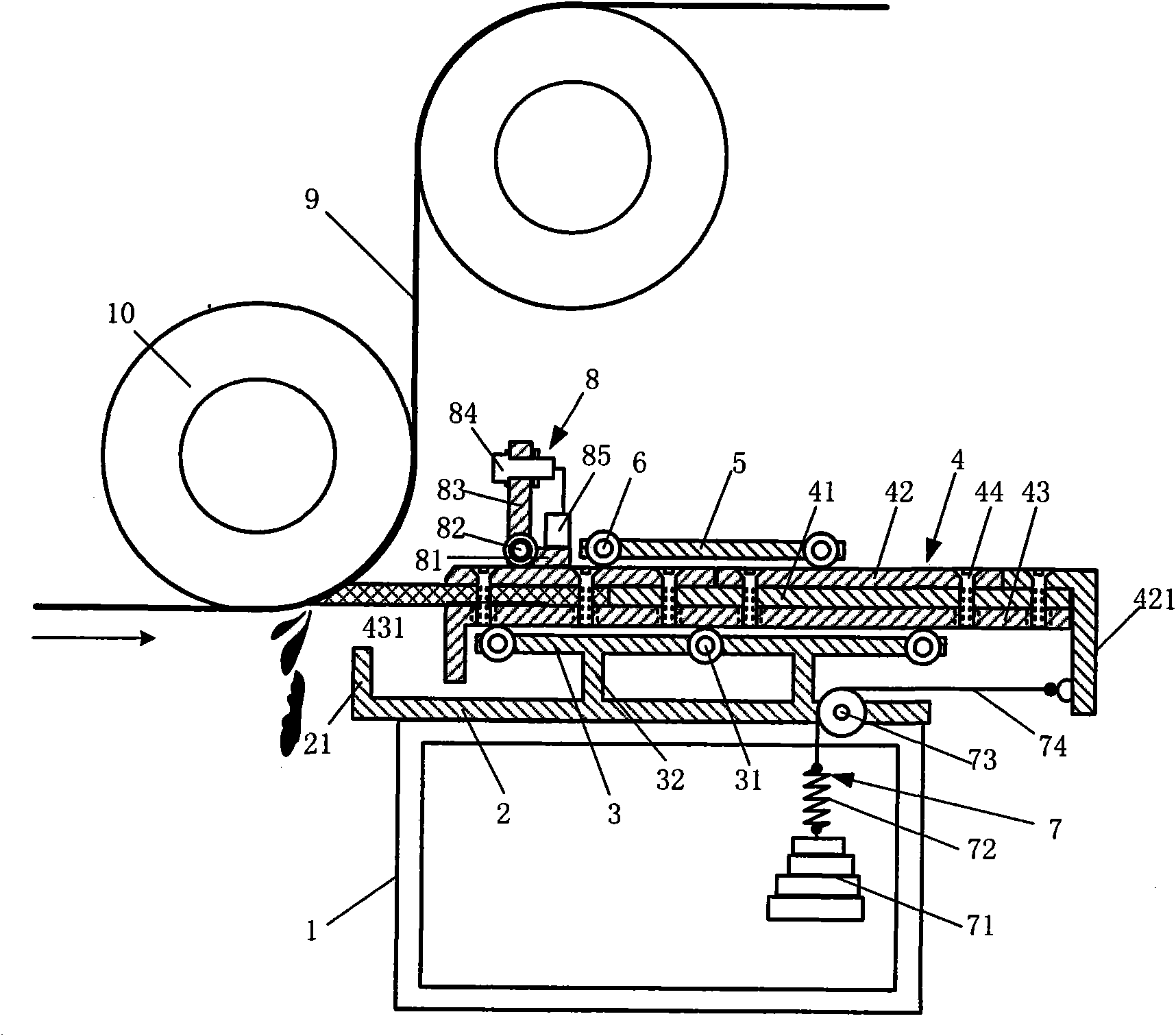
[0021] see figure 1 , figure 2 , the self-propelled and compensated reverse conveyor belt cleaner of the present invention includes a base 1; a base plate 2 is arranged on the base 1, and one end of the conveyor belt protrudes from the base 1 and bends upward to form a stop where the cleaner reaches the limit position. Position stopper 21; the lower idler seat 3 is fixed on the bottom plate 2 through a bracket 31, and several idler rollers 32 are arranged along the length direction of the lower idler seat;

[0022] The cleaner frame 4 is set on the idler roller 32 of the lower idler seat, including the cleaning rubber 41, the upper and lower splints 42, 43 and bolts 44 clamping the cleaning rubber 41; the end of the lower splint 43 close to the conveyor belt extends out of the lower idler seat 3 and bent downward to form a synchronous shift block 431 of the cleaner, corresponding to the stop block 21 of the bottom plate 2; the upper splint 42 is bent downward to form a fixed...


PUM


Abstract

The invention discloses a self-propelled compensating return stroke sweeper for a conveying belt, and the self-propelled compensating return stroke sweeper for the conveying belt comprises a base, a bottom plate, a lower carrier roller seat, a sweeper framework, an upper carrier roller seat, a self-propelled compensating return stroke mechanism and an alarming mechanism, wherein the bottom plate is arranged on the base; one end of the bottom plate is bent upwards to form a limiting stop dog; the lower carrier roller seat is fixed on the bottom plate; the sweeper framework comprises a sweepingrubber eraser, an upper splint, a lower splint and a bolt; the lower splint is bent downwards to form a synchronous shifting stop dog; the upper carrier seat is positioned on the upper splint of the sweeper framework; the self-propelled compensating return stroke mechanism comprises a counterweight, a buffering spring, a hanging steel wire and a fixed pulley; the fixed pulley is fixed on the base; the buffering spring is connected with the counterweight; the other end of the buffering spring is connected with the hanging steel wire; the other end of the hanging steel wire is wound on the fixed pulley and is connected with the fixing part of the upper splint; the alarming mechanism comprises the bottom plate, a fixing bracket connected with the pivot shaft of the bottom plate, a proximity switch fixed on the fixing bracket, and an alarm connected with the proximity switch. The self-propelled compensating return stroke sweeper for the conveying belt has a self-propelled compensation function for the sweeping rubber eraser, the sweeping rubber eraser can be flexibly adjusted when the conveying belt has an uneven surface, and equal pressure is guaranteed to be applied to the surface of the running conveying belt.

Description

technical field [0001] The invention relates to a transportation machine, in particular to a self-propelled compensation conveyor belt reverse cleaning device for a belt conveyor. Background technique [0002] The mineral materials conveyed by the bulk mineral conveyor belt are often viscous when the climate is humid; such as mud, powdery materials, etc., some of which will stick to the working surface of the conveyor belt and cannot be removed during unloading, and the sticky materials will enter (Reverse travel) The lower idler roller in the empty section, dirty the idler roller and make it enter the idler body. The adverse consequences are to increase the radial load and axial load on the bearing seat, causing rapid wear of the bearing, and the surface glue of the conveyor belt will be torn and roughened by the material sticking to the idler shell, which will accelerate the wear of the conveyor belt. If the sticky matter enters the tail reversing roller, it will stick to...

Claims


Application Information

Patent Timeline
Patent Type & Authority Applications(China)
IPC IPC(8): B65G45/14
Inventor 李斌孔利明
Owner BAOSHAN IRON & STEEL CO LTD
Why Eureka
Try Eureka