

Storage battery lift truck driving motor braking apparatus
A technology for driving motors and braking devices, applied in the direction of electromechanical devices, electric components, electrical components, etc., can solve the problems of lowering the working efficiency of lift trucks, prone to overshooting, and waste of manpower, so as to save manpower, improve work efficiency, The effect of simple structure
- Summary
- Abstract
- Description
- Claims
- Application Information
AI Technical Summary
Problems solved by technology
Method used
Image

Examples
Embodiment Construction
[0012] The braking device for driving the motor of the battery lift car of the present invention will be further described in detail through specific embodiments below.
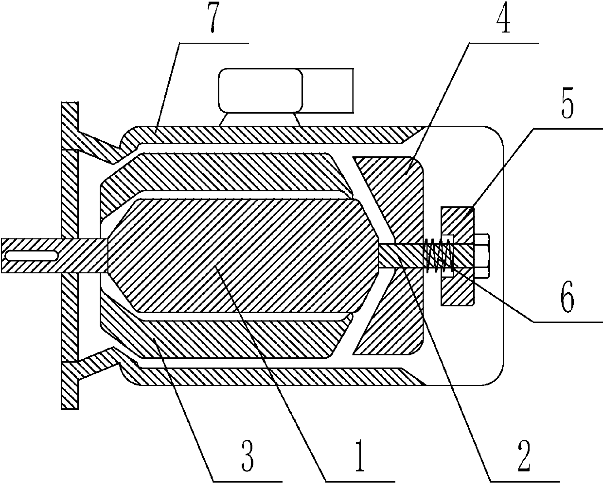
[0013] Such as figure 1 As shown, the motor brake device driven by the battery lift car includes an elongated shaft 2 arranged at the rear end of the rotor 1 of the motor and a stator 3 sleeved outside the rotor 1 of the motor. The elongated shaft 2 is sequentially provided with cones Shaped iron 4 and electromagnet 5, spring 6 is arranged between conical iron 4 and electromagnet 5, and described extension shaft 2, stator 3, conical iron 4, electromagnet 5 and spring 6 are all arranged on the motor Shell 7.
[0014] The working principle of the present invention is: when the motor is energized and needs to run, the electromagnet 5 is energized to generate magnetism to adsorb the conical iron 4. At this time, the spring 6 is in a compressed state, and the conical iron 4 rotates synchronously with the rotor 1...
PUM
 Abstract
Description
Claims
Application Information