

Pipe connecting device
A technology of pipe reels and pipe reels, which is applied in mining equipment, earthwork drilling, tunnels, etc., and can solve problems that affect the construction progress, time-consuming, labor-intensive, and difficult connections
- Summary
- Abstract
- Description
- Claims
- Application Information
AI Technical Summary
Problems solved by technology
Method used
Image

Examples
Embodiment Construction
[0017] Preferred embodiments of the present invention will be described in detail below in conjunction with the accompanying drawings.
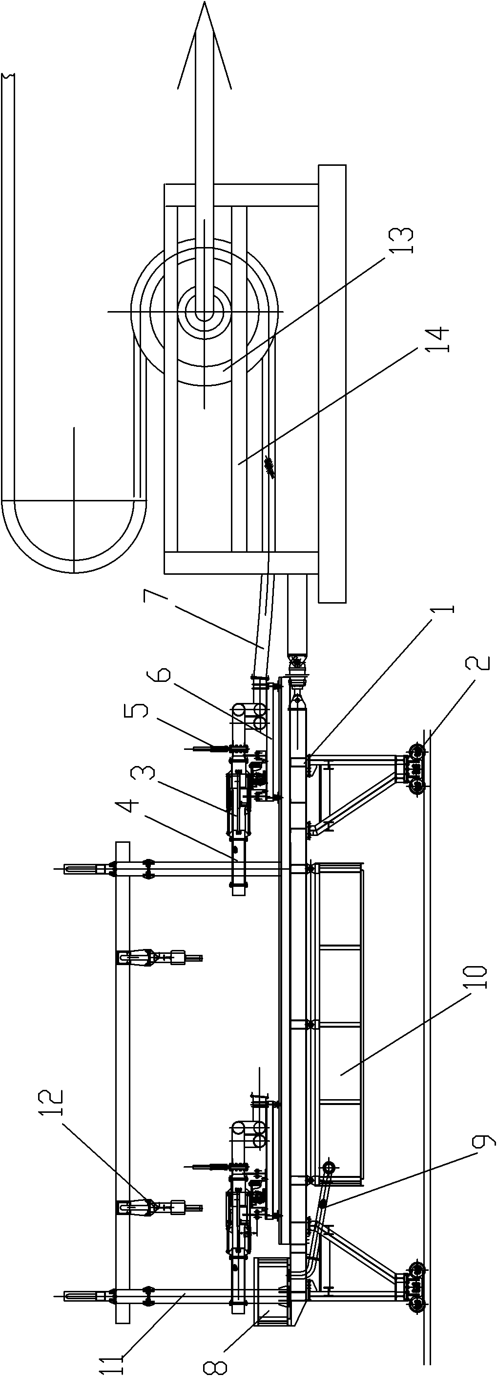
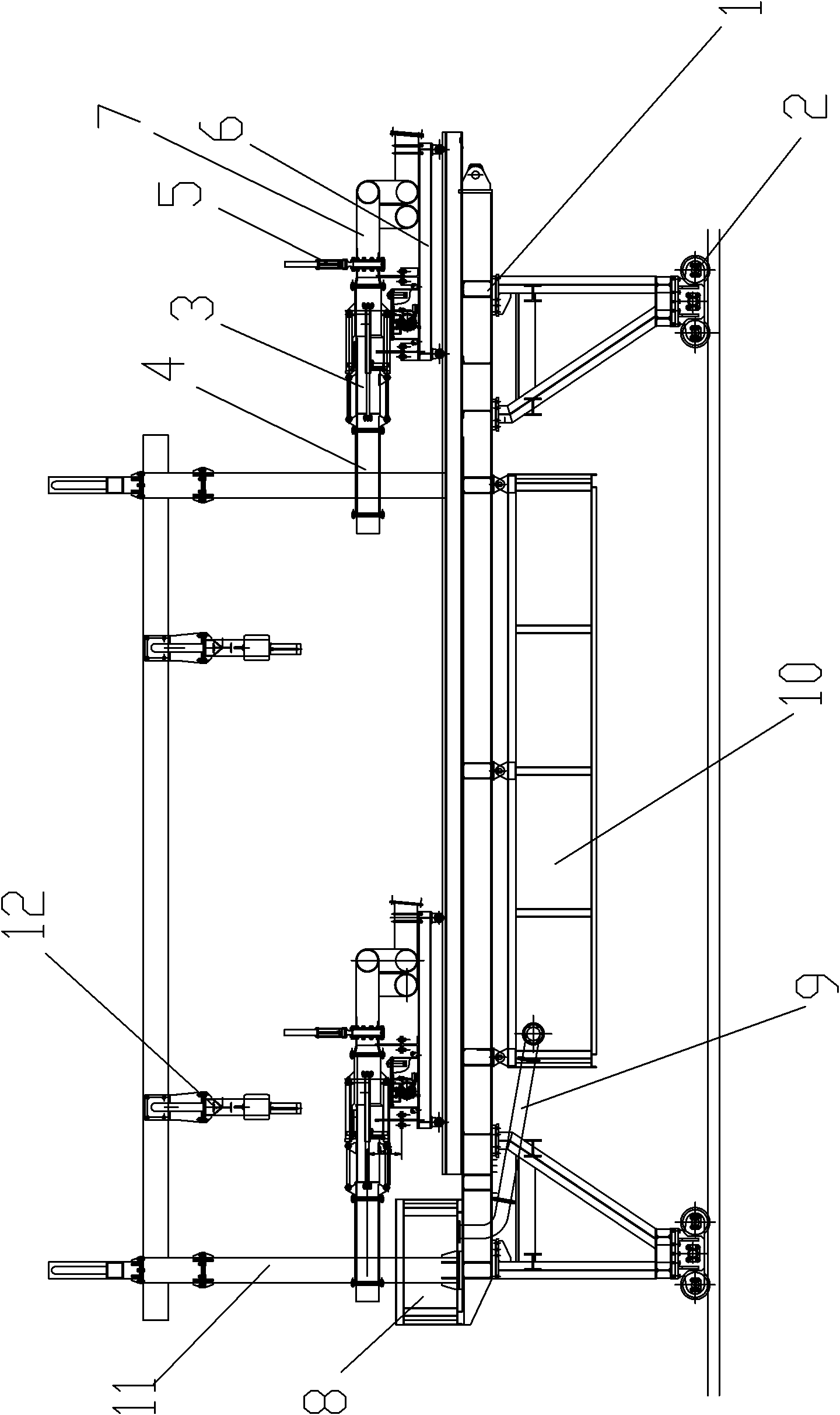
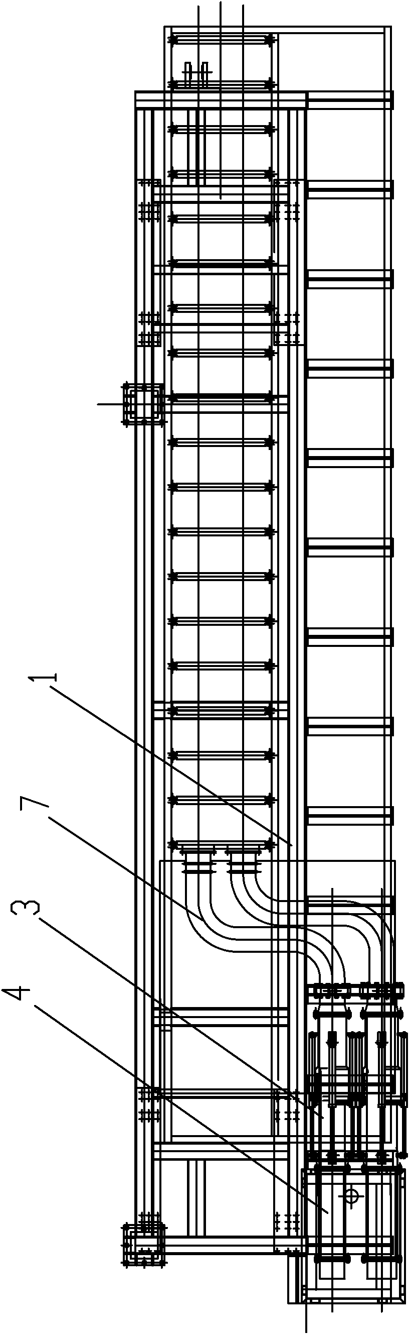
[0018] Such as figure 1 , 2 , 3, the adapter includes a main frame 1, the bottom of the main frame 1 is provided with rollers 2, and the main frame 1 can slide back and forth. The main frame 1 is provided with two pipeline fine-tuning devices 3 side by side. The pipeline fine-tuning device 3 is located on a sliding trolley 6, which is located on the main frame 1, and the sliding trolley 6 can slide back and forth on the main frame 1. Such as Figure 4 As shown, the pipeline fine-tuning device 3 includes an inner cylinder 32 and an outer cylinder 31, the inner cylinder 32 is located in the outer cylinder 31, and the upper and lower sides of the outer cylinder 31 are respectively provided with a hydraulic hydraulic cylinder 33, and the hydraulic pressure of the hydraulic hydraulic cylinder 33 The piston rod 34 of the oil cylinder is connecte...
PUM
 Abstract
Description
Claims
Application Information