Magnetic component assembly

A technology of magnetic components and components, applied in the direction of inorganic material magnetism, transformer/inductor components, electrical components, etc., can solve the problems of increasing the cost of electronic components and expensive manufacturing processes.

Inactive Publication Date: 2012-05-16
COOPER TECH CO
View PDF2 Cites 10 Cited by
  • Summary
  • Abstract
  • Description
  • Claims
  • Application Information

AI Technical Summary

Problems solved by technology

Manufacturing electronic components to meet these demands presents many difficulties, thus making the manufacturing process more expensive and undesirably increasing the cost of electronic components

Method used


Image

  • Magnetic component assembly
  • Magnetic component assembly
  • Magnetic component assembly

Examples


Embodiment Construction

[0027] Example embodiments of inventive electronic component designs are described herein that overcome various challenges in the art. For the most complete understanding of the present invention, the following disclosure has various sections or sections, with Section I discussing specific issues and challenges, and Section II describing example component configurations and assemblies for overcoming these issues.

[0028] I. Introduction to the Invention

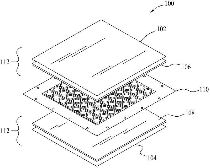
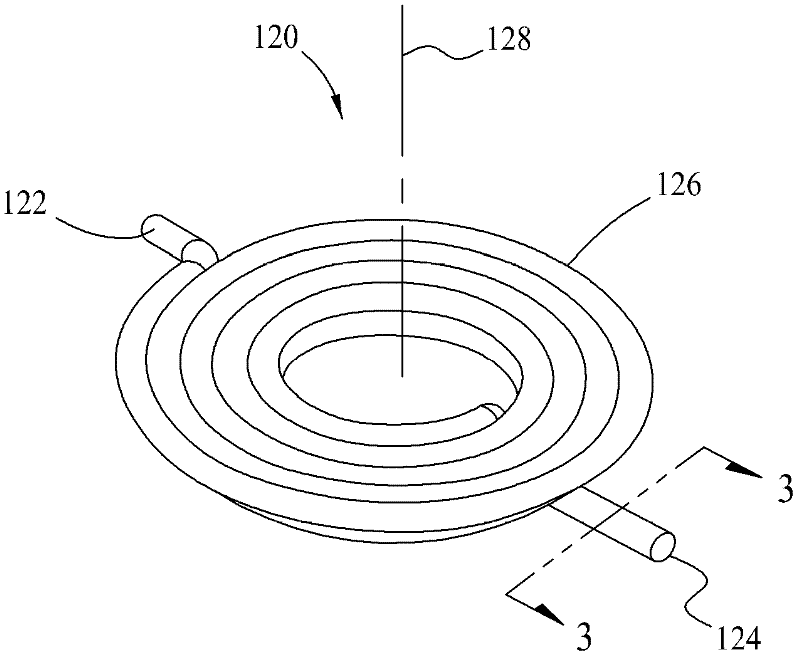
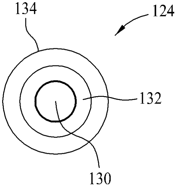
[0029] Conventional magnetic components, such as inductors, used in circuit board applications typically include a magnetic core and a conductive winding (sometimes called a coil) within the magnetic core. The core may be made of discrete core parts made of magnetic material with the windings placed between the core parts. Various shapes and types of core components and assemblies are known to those skilled in the art, including but not necessarily limited to U-core and I-core assemblies, ER-core and I-core assemblies, ER-c...


PUM


Abstract

Magnetic component assemblies including moldable magnetic materials formed into magnetic bodies, at least one conductive coil, and termination features are disclosed that are advantageously utilized in providing surface mount magnetic components such as inductors and transformers.

Description

Background technique [0001] The field of the invention relates generally to magnetic components and their manufacture, and more particularly to magnetic surface mount electronic components such as inductors and transformers. [0002] With advances in electronic packaging, it has become feasible to manufacture smaller but more powerful electronic devices. In order to reduce the overall size of these electronic devices, the electronic components used to manufacture these electronic devices have become increasingly miniaturized. Manufacturing electronic components to meet these demands presents many difficulties, thus making the manufacturing process more expensive and undesirably increasing the cost of the electronic components. [0003] Like other components, manufacturing processes for magnetic components such as inductors and transformers have been scrutinized to reduce costs in the highly competitive electronics manufacturing industry. This is especially desirable for redu...

Claims


Application Information

Patent Timeline
Patent Type & Authority Applications(China)
IPC IPC(8): H01F17/04H01F27/29H01F27/30
CPCH01F17/0006H01F2017/048H01F3/10H01F27/2847H01F17/04H01F1/33H01F41/0233H01F41/046Y10T29/49073H01F41/02
Inventor 颜毅鹏R·J·博格特
Owner COOPER TECH CO
Why Eureka
Try Eureka