Material torsion testing machine

A technology of torsion testing machine and driving column, applied in the direction of analyzing materials, measuring devices, instruments, etc., can solve the problems of high cost, poor test accuracy, large error, etc., and achieve the effect of eliminating cumulative error, good product quality, and simple structure

Active Publication Date: 2012-06-27
ZHEJIANG SHITAI IND CO LTD
View PDF5 Cites 12 Cited by
  • Summary
  • Abstract
  • Description
  • Claims
  • Application Information

AI Technical Summary

Problems solved by technology

[0002] At present, there are roughly two types of material testing machines used in the society: one is the precision type, although this type of material testing machine has high testing accuracy and many functions, but its structure is complicated, the operation is difficult, and the cost is high. The second type is the common type. This type of material testing machine has a simple structure and low cost, but its test accuracy is poor, the error is large, the test is not accurate, and it cannot meet the requirements of use. The main reason is: due to the torsion , The strength of the tension and compression test is relatively large, and all stressed parts such as the base, workbench, drive column, guide column, top beam connection, movable beam, etc. will have different degrees of plastic deformation during the process of torsion, tension and compression of the workpiece. The combination of deformation leads to a large error between the real deformation of the workpiece and the displayed deformation, and the accuracy of the ordinary material testing machine is low, and it costs less money to perform high-precision material testing with ordinary material testing machines. Urgent needs of users

Method used


Image

  • Material torsion testing machine
  • Material torsion testing machine
  • Material torsion testing machine

Examples


Embodiment Construction

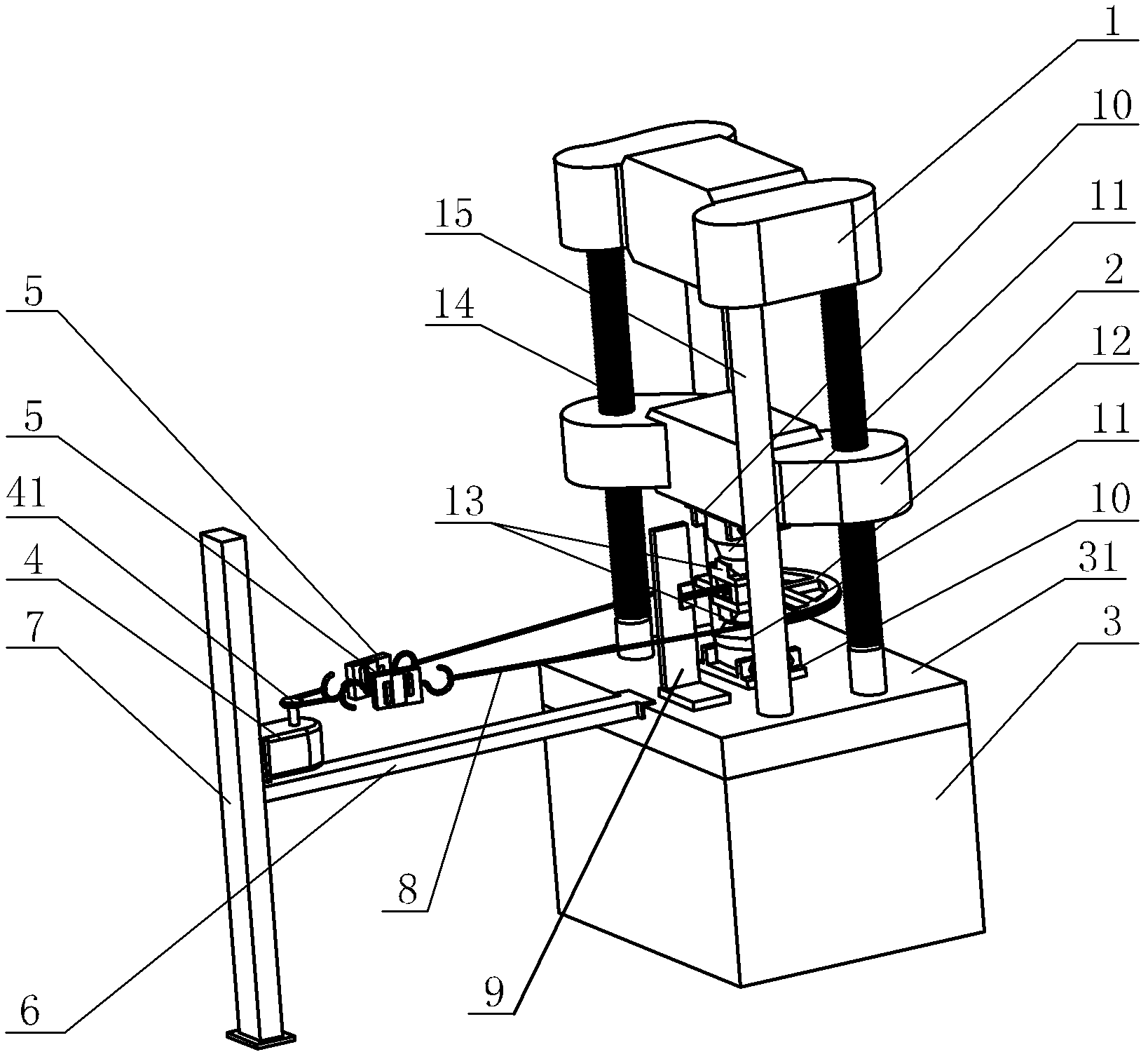
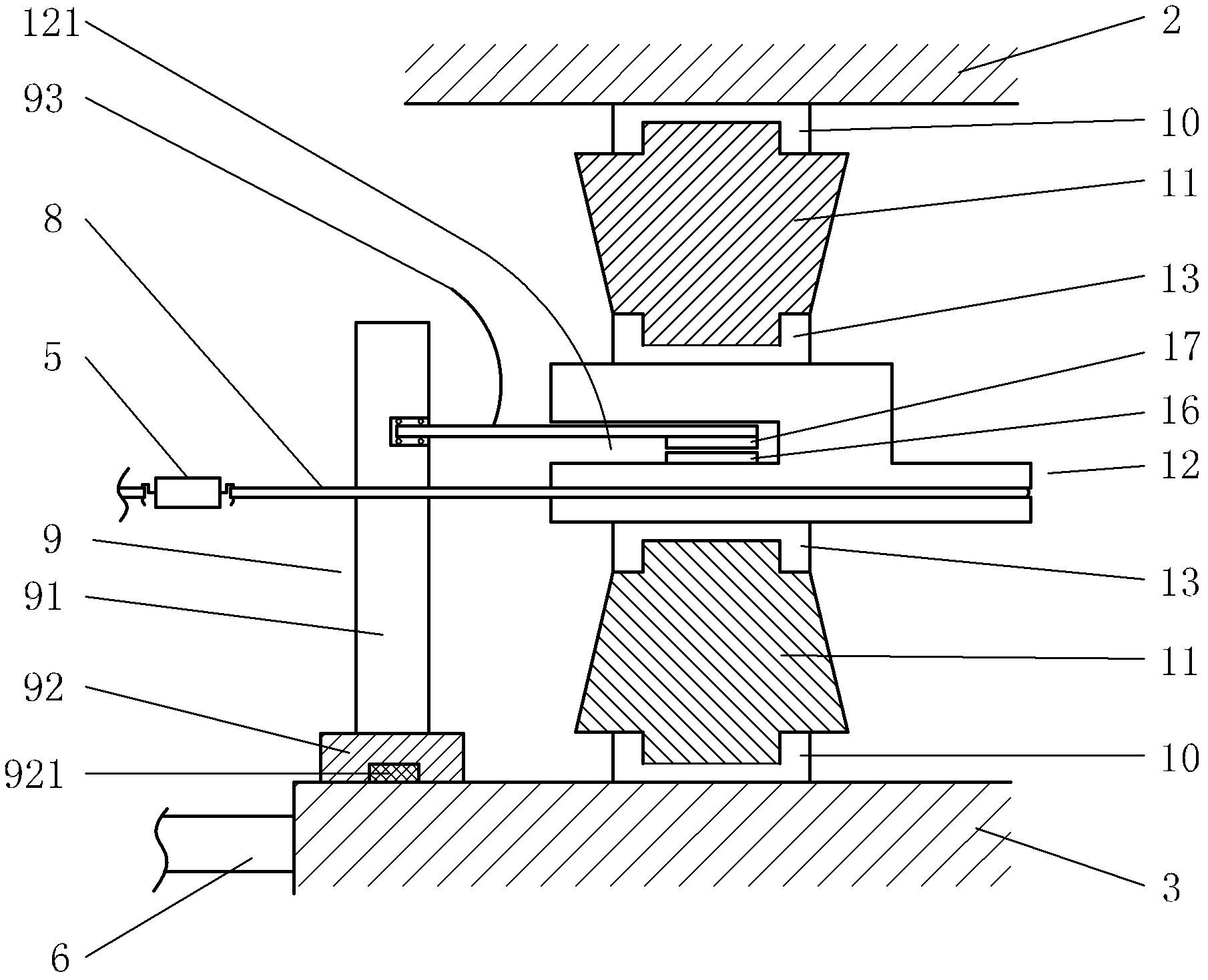
[0019] Below in conjunction with accompanying drawing, the present invention will be further described with specific embodiment, see Figure 1-2 :

[0020] A material torsion testing machine, the base 3 is provided with a drive column 14 and a column 15, the drive column 14 and the column 15 are arranged parallel to each other and perpendicular to the upper table 31 of the base 3, the upper end of the column 15 is connected to the top beam 1, A movable beam 2 is arranged between the top beam 1 and the base 3, and the movable beam 2 is driven to move up and down by the driving column 14 driven by the power device. Fixing seats 10 for installing the workpiece 11 to be tested are respectively arranged on the surface, and a turntable 12 is arranged between the two fixing seats 10. The upper and lower ends of the turntable 12 are respectively provided with fixing positions 13 for installing the workpiece 11 to be tested. The middle parts of the two fixing positions 13 A sensor ins...


PUM


Abstract

The invention belongs to the field of material testing machines, relates to a material torsion testing machine. Driving posts and upright posts are arranged on a base; the upper ends of the upright posts are connected with a top beam; a movable cross beam is arranged between the top beam and the base; fixing seats for a to-be-tested work piece are arranged on the base and the movable cross beam or on the movable cross beam and the top beam respectively; a rotating table is arranged between the two fixing seats; fixing positions are arranged at the upper and the lower ends of the rotating table respectively; a sensor mounting cavity is arranged at the middle of the two fixing positions; an angle sensor rotating part is arranged on the rotating table on one side of the sensor mounting cavity; a cantilever of a mounting frame on an upper platform surface of the base extends to the sensor mounting cavity and is mounted with an angle sensor fixing component in a suspending manner; a motor is fixed on a vertical beam on one side of the base; the motor is connected with the rotating table through a steel cable or a chain; a left tractive force sensor and a right tractive force sensor are connected onto the steel cable or the chain in series; and the tractive force sensors and an angle sensor are connected with a computer through signal wires. The material torsion testing machine has the advantages of high testing precision, low equipment cost, and suitability for high-precision detection for work pieces.

Description

technical field [0001] The invention belongs to the technical field of material testing machines, and in particular relates to a material torsion testing machine which uses simple equipment to measure high-precision torsional deformation of workpieces. Background technique [0002] At present, there are roughly two types of material testing machines used in the society: one is the precision type, although this type of material testing machine has high testing accuracy and many functions, but its structure is complicated, the operation is difficult, and the cost is high. The second type is the common type. This type of material testing machine has a simple structure and low cost, but its test accuracy is poor, the error is large, the test is not accurate, and it cannot meet the requirements of use. The main reason is: due to the torsion , The strength of the tension and compression test is relatively large, and all stressed parts such as the base, workbench, drive column, gui...

Claims


Application Information

Patent Timeline
Patent Type & Authority Applications(China)
IPC IPC(8): G01N3/26
Inventor 陈中敢陈建会
Owner ZHEJIANG SHITAI IND CO LTD
Why Eureka
Try Eureka