Light-emitting diode (LED) light source device

A technology for light emitting diodes and light source devices, which is applied in electrical components, electrical solid state devices, circuits, etc., and can solve problems such as inability to adjust

Active Publication Date: 2012-11-28
中山市成源光电科技有限公司
View PDF3 Cites 3 Cited by
  • Summary
  • Abstract
  • Description
  • Claims
  • Application Information

AI Technical Summary

Problems solved by technology

However, since the relative position between the packaged LED chip and the phosphor layer is fixed, the color temperature of the light emitted by the LED light source is also fixed, which cannot be adjusted, and cannot meet actual needs.

Method used


Image

  • Light-emitting diode (LED) light source device
  • Light-emitting diode (LED) light source device
  • Light-emitting diode (LED) light source device

Examples


Embodiment approach 1

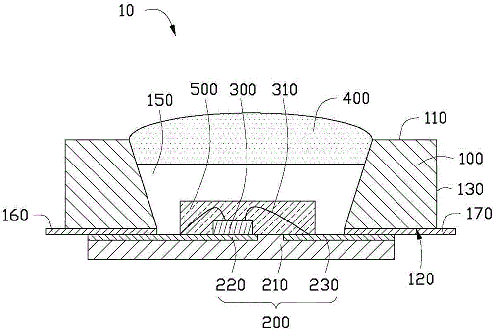
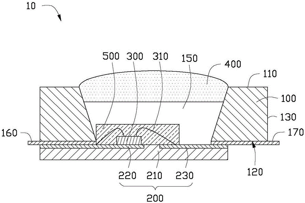
[0016] see figure 1 as well as figure 2 A light-emitting diode light source device 10 provided in a preferred embodiment of the present invention includes a base 100, a base plate 200 disposed on the base 100, a light-emitting diode chip 300 disposed on the base plate 200, and a cover. The phosphor layer 400 of the LED chip 300 is described above.

[0017] The base 100 includes a top surface 110 , a bottom surface 120 , two opposite end surfaces 130 and two opposite side surfaces 140 . The base 100 runs through the entire base 100 from the top surface 110 along the bottom surface 120 to form an accommodating groove 150 . The accommodating groove 150 is used to provide an accommodating space for the LED chip 300 and the phosphor layer 400 and to set the light field of the LED light source device 10 . The inner surface of the accommodation groove 150 is an inclined surface, which extends from the top surface 110 to the bottom surface 120 and inclines inward along the radial ...

Embodiment approach 2

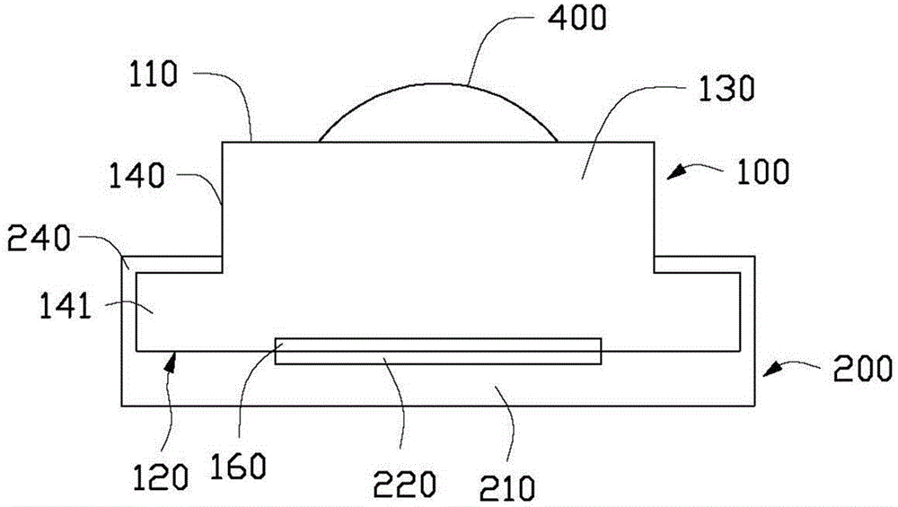
[0027] see Figure 5 The difference between the LED light source device 20 provided in the second embodiment of the present invention and the LED light source device 10 provided in the first embodiment is that no electrodes are formed on the bottom surface of the base 100a, and the third electrode 220a and the third electrode 220a on the bottom plate 200a One ends of the four electrodes 230a respectively extend out of the bottom plate 200a for connection with external circuits. The base 100a is movably disposed on the base plate 200a, and can slide relative to the base plate 200a, so as to adjust the relative position of the phosphor layer 400 and the LED chip 300 on the base plate 200a.

[0028] Compared with the prior art, the light-emitting diode light source device of the present invention is provided with a phosphor layer with non-uniform thickness distribution, and by changing the relative position of the light-emitting diode chip and the phosphor layer, the light-emitti...


PUM


Abstract

The invention provides a light-emitting diode (LED) light source device. The device comprises a bottom board, an LED chip and a base, wherein the LED chip is arranged on the bottom board; the base is connected with the bottom board in a sliding manner; a fluorescent powder layer is arranged on the base, is arranged in the direction shielding light emergence of the LED chip and is non-uniformly distributed in thickness. The bottom board and the base can slide relatively to ensure that the LED chip corresponds to parts of the fluorescent powder layer having different thicknesses, thus changing the color temperature of the emergent light of the LED light source device.

Description

technical field [0001] The invention relates to an illuminating device, in particular to a light emitting diode light source device. Background technique [0002] Light-emitting diodes are energy-saving, environmentally friendly, and long-life solid-state light sources. Therefore, the research on light-emitting diode technology has been very active in the past ten years, and light-emitting diodes are gradually replacing traditional light sources such as fluorescent lamps and incandescent lamps. In the prior art, the light emitting diode light source device generally installs the light emitting diode chip on the circuit board, and then uses the encapsulation gel doped with phosphor to encapsulate the light emitting diode, and the light emitted by the light emitting diode chip excites the phosphor powder to be emitted to the light source. external. However, since the relative position of the packaged LED chip and the phosphor layer is fixed, the color temperature of the light...

Claims


Application Information

Patent Timeline
Patent Type & Authority Applications(China)
IPC IPC(8): H01L33/48H01L33/50H01L33/62
CPCH01L2224/48091H01L2224/48247
Inventor 林新强
Owner 中山市成源光电科技有限公司
Why Eureka
Try Eureka