
Couple-part symmetry-degree zero-error positioning device
A positioning device and zero-error technology, which is applied in the field of positioning fixture devices for even parts, can solve problems such as limiting the machining accuracy of even parts and affecting product quality, and achieve the effects of low cost, simple structure and wide application range
- Summary
- Abstract
- Description
- Claims
- Application Information
AI Technical Summary
Problems solved by technology
Method used
Image

Examples
Embodiment Construction
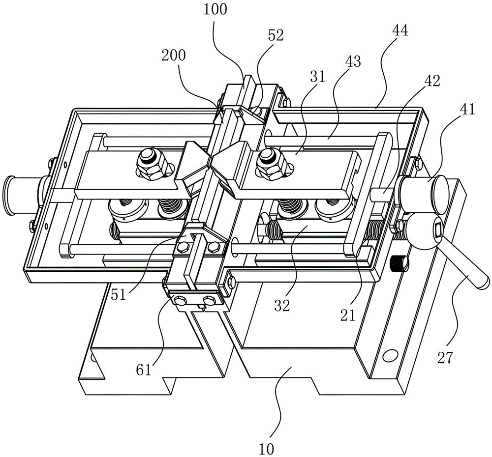
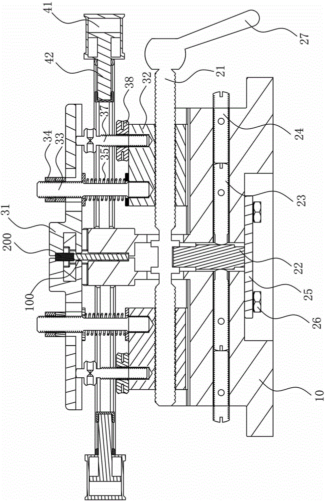
[0059] See Figure 1 to Figure 8 As shown, it shows the specific structure of the preferred embodiment of the present invention, which includes a base 10, a positioning component, two clamping adjustment components and two pneumatic clamping components.
[0060] Such as Figure 8 As shown, the positioning assembly includes a rotating positioning screw 21, the rotating positioning screw 21 has a first threaded portion 211, a second threaded portion 212 and a pivoting portion 213 between the first threaded portion 211 and the second threaded portion 212 The first threaded part 211 and the second threaded part 212 are located at the left and right ends of the positioning screw 21 respectively and their threading directions are opposite. The pivoting part 213 is rotatably nested in the base 10 and the first threaded part 211 Both the second threaded part 212 and the second threaded part 212 are exposed outside the base, the aforementioned base 10 is provided with a limiting mecha...
PUM
 Abstract
Description
Claims
Application Information