Movable joint mechanism for mechanical arm

A technology of movable joints and robotic arms, which is applied in the direction of manipulators, manufacturing tools, joints, etc., can solve the problems of easy failure of the movable joint mechanism of the mechanical arm, and achieve the effect of easy assembly, not easy to fail, and convenient use

Inactive Publication Date: 2013-07-03
BEIJING AEONMED
View PDF9 Cites 1 Cited by
  • Summary
  • Abstract
  • Description
  • Claims
  • Application Information

AI Technical Summary

Problems solved by technology

[0004] The purpose of the present invention is to provide a mechanical arm movable joint mechanism to solve the problem that the existing mechanical arm movable joint mechanism is prone to failure

Method used


Image

  • Movable joint mechanism for mechanical arm
  • Movable joint mechanism for mechanical arm
  • Movable joint mechanism for mechanical arm

Examples


Embodiment Construction

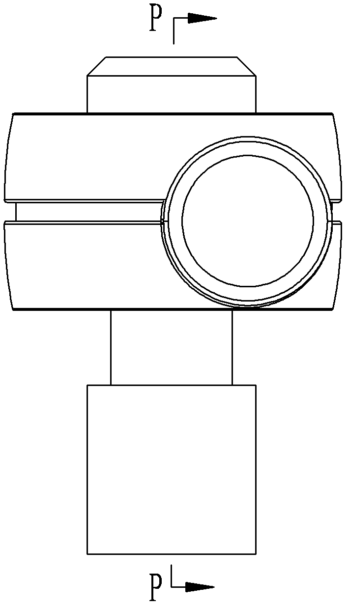
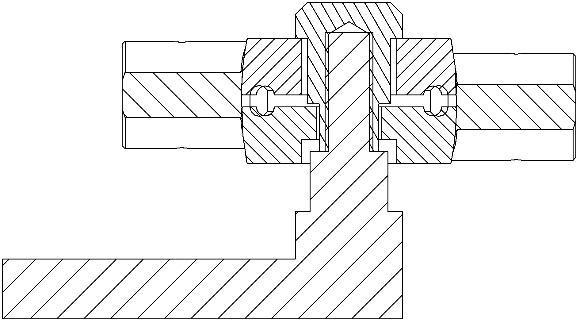
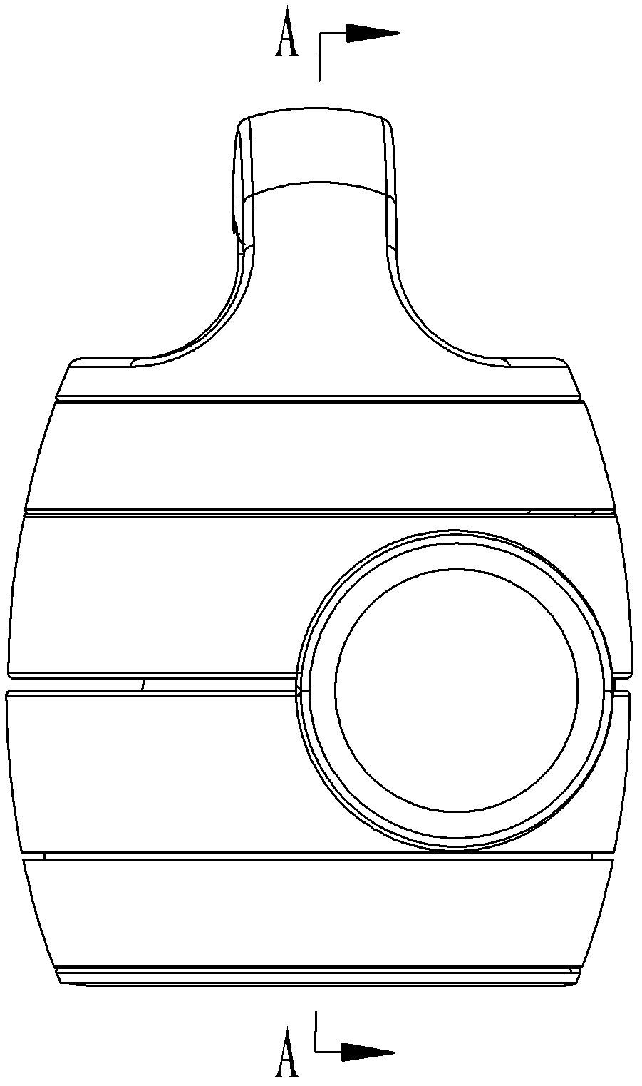
[0020] Such as Figure 3-5 As shown, the movable joint mechanism of the mechanical arm in this embodiment includes a first rotary buckle 1 and a second rotary buckle 2, and the first rotary buckle 1 and the second rotary buckle 2 are buckled by a tapered surface in the axial direction, and The degree of tightness of the fastening is adjusted through the threaded connection structure. A gap is left between the ends of the conical surfaces, and the first rotary buckle 1 and the second rotary buckle 2 are provided with connecting parts for connecting the mechanical arms on their respective revolving surfaces that are not the conical surfaces.

[0021] The connecting part is in the shape of a cylinder, and a connecting part installation hole penetrating through the cylinder is arranged radially on it, and the connecting part is used for fixedly connecting the mechanical arm with the connecting part.

[0022] The threaded connection structure is a threaded hole opened in the cente...


PUM


Abstract

The invention discloses a movable joint mechanism for a mechanical arm, which comprises a first rotary buckle and a second rotary buckle, wherein the first rotary buckle and the second rotary buckle are fastened with each other in the axial direction through conical surfaces, and the fasten tightness is adjusted through a threaded connecting structure; intervals are arranged between the end part of the first rotary buckle conical surface and the root part of the second rotary buckle conical surface, and between the root part of the first rotary buckle conical surface and the end part of the second rotary buckle conical surface; revolution surfaces, not the conical surfaces, of the first rotary buckle and the second rotary buckle are respectively provided with a connecting part for connecting a mechanical arm. The movable joint mechanism solves the problem that the movable joint mechanism of the conventional mechanical arm is easy to invalidate, convenient and reliable to use, less susceptible to invalidate and easy to assemble; and has beautiful, delicate and generous appearance.

Description

technical field [0001] The invention relates to a joint mechanism, in particular to a movable joint mechanism of a mechanical arm. Background technique [0002] Existing mechanical arm movable joint mechanism (see figure 1 and figure 2 ) is made of two completely symmetrical fastening bodies with semicircular grooves, and a copper ring is locked in the middle. The copper ring is larger and deeper than the semicircular groove, and several through holes are punched on the two contacting semicircular surfaces of the copper ring to increase the friction of the contact surface. When the two fastening bodies are fastened together, the copper ring is squeezed and a certain gap is opened. The existence of this gap makes the two fastening bodies tightened by screws and kept fixed at a certain position in space under the action of friction. . [0003] The feature of the above structure is to prop up the gap between the two fastening bodies according to the semicircular surface an...

Claims


Application Information

Patent Timeline
Patent Type & Authority Applications(China)
IPC IPC(8): B25J17/00
Inventor 东志翔任福立
Owner BEIJING AEONMED
Why Eureka
Try Eureka