Tray with limit structure

A technology of limiting structure and tray, applied in rigid containers, packaging of fragile items, containers, etc., can solve the problems of COF2 pulling damage, COF damage, and inability to use OpenCellB6, and achieve the effect of expanding compatibility

Active Publication Date: 2013-08-14
TCL CHINA STAR OPTOELECTRONICS TECH CO LTD
View PDF7 Cites 19 Cited by
  • Summary
  • Abstract
  • Description
  • Claims
  • Application Information

AI Technical Summary

Problems solved by technology

Open Cells are generally placed flat on the tray, and the positioning device of the tray positions the Open Cell around, because when the Open Cell is subjected to vibration, the PCB board is likely to move with the vibration and pull the COF, resulting in damage to the COF, thus affecting the product quality, and the COF is a flexible sheet, the PCB board is easily brought into two LCD boxes by vibration
In the current Open Cell packaging method, the blister tray is directly formed with columns, such as figure 1 , figure 2 As shown, Open Cell A1 has only one COF2, and the tray 4 uses two pillars 5 to block the PCB board 3. This method is only suitable for placing a single tray with a small number of Open Cells. Once the number of Open Cells is large, the pillars 5 will be more High, due to the obstruction of the pillar 5, when installing the Open Cell and taking the Open Cell, it is easy to hang the PCB board 3 on the pillar 5, which will cause the COF2 to be pulled and damaged, which will affect the product quality
The current design of the number of sheets for a single tray is 4 pieces, and this column 5 that has been formed when the tray 4 is produced is not suitable for the commonality of the tray 4. image 3 , if the tray 4 is used to hold the Open Cell B6, the Open Cell B6 has multiple COFs connected to the PCB board 8, and the middle two COF7 will interfere with the two columns 5 of the tray 4, so that the tray 4 cannot be used Install Open Cell B6
Therefore, if you want to install Open Cell B6, you need to re-open a mold for Open Cell B6 to produce the corresponding tray, which causes a waste of mold cost, and this tray is recycled, if not shared, it will cause Waste of packaging resources increases the cost of production

Method used


Image

  • Tray with limit structure
  • Tray with limit structure
  • Tray with limit structure

Examples


Embodiment 1

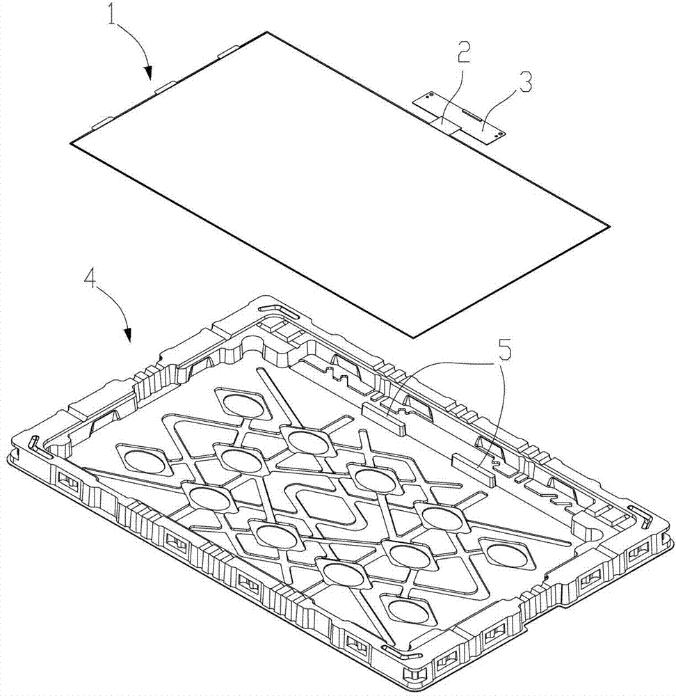
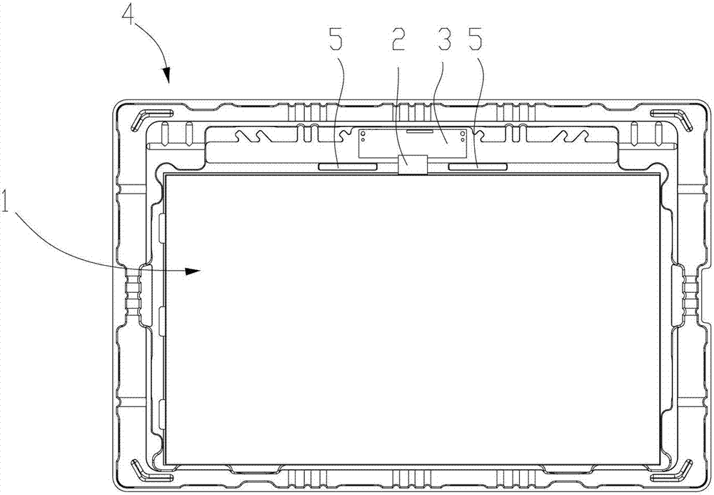
[0022] Such as Figure 4 , Figure 5 As shown, the tray for placing the Open Cell of the LCD screen includes a tray body 10, the tray body 10 is provided with a groove 11 for placing the Open Cell, the Open CellA20 is placed in the groove 11, and the Open Cell A20 is connected by a COF21 Liquid crystal box 22, PCB board 23 form. In addition, it also includes a buckle 30, see also Figure 6 , The buckle 30 is composed of two mutually hinged components, namely a fixing component 31 and a buckling component 32 . The fixing member 31 includes a fixing part 311 and a receiving part 312, which are integrally formed in a stepped shape, and 32 buckle members are hinged at the steps, and when the buckle member 32 rotates toward the receiving part 312, it finally fits on the receiving part 312. On the surface, this can prevent the buckle member 32 from directly pressing on the PCB board 23 , and also keep the installation effect of the two buckle parts 30 assembled on both sides of t...

Embodiment 2

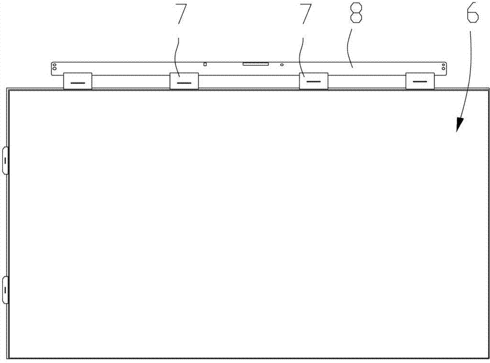
[0025] This embodiment differs from Embodiment 1 in the structure of the buckle, and other similar structures will not be repeated here. Such as Figure 7 As shown, the buckle 50 is hinged by a fixing member 51 and a buckling member 52 . This structure makes it possible for the buckle member 52 to be pressed against the PCB without being restricted by the receiving portion as in Embodiment 1 when it rotates downward. Therefore, the length of the buckle part 53 in the buckle member can be designed to be long enough, so that when the end of the buckle part 53 is inserted into the bottom surface of the tray, it can avoid being pressed against the PCB. Similarly, a layer of antistatic buffer gasket 41 is provided on the outer surface of the buckle part 53 , and an adhesive is provided on the side surface 54 of the fixing member 51 to adhere to the inner wall of the tray body.


PUM


Abstract

A tray with a limit structure is used for holding an Open Cell of a liquid crystal display. The tray comprises a tray body, and a groove for holding the Open Cell is arranged in the tray body. The tray with the limit structure is characterized by further comprising a fastener, the fastener comprises a fixing component connected with the tray body and a fastening component movably connected with the fixing component. The fastening is connected with the tray body in an adhering manner, can be mounted when needed or can be dismounted when not needed, and compatibility of the tray utilization is broadened. The fastening component is firstly lifted up around a hinged shaft before the Open Cell is dismounted, at this time, a PCB (printed circuit board) and a COF (chip on film) are in a relatively open state, the Open Cell is not blocked by external factors when being used, so that damages caused on the COF are prevented.

Description

technical field [0001] The invention relates to a tray for placing an Open Cell of a liquid crystal screen, in particular to a tray provided with a limiting structure. Background technique [0002] At present, there are various packaging methods for liquid crystal panels in the industry, some with blister trays as the main body, some with injection molded boxes as the main body, and some with foam products as the main body; there are two types of liquid crystal panels: The form of existence is defined by the industry as Cell and Open Cell respectively. Cell is a liquid crystal box formed by sandwiching two glass substrates with a liquid crystal seal assembly. Its appearance is the same as ordinary thin glass. Open Cell is configured on the basis of Cell. Interface for external signal sources, etc., but Open Cell does not include backlight, frame and other components in the liquid crystal module (LCM, liquid crystal module). [0003] Usually, Open Cell connects more than one...

Claims


Application Information

Patent Timeline
Patent Type & Authority Applications(China)
IPC IPC(8): B65D85/30B65D19/22B65D19/38B65D81/127
CPCB65D81/027B65D85/30
Inventor 胡乾双
Owner TCL CHINA STAR OPTOELECTRONICS TECH CO LTD
Why Eureka
Try Eureka