Ceiling Antenna

A ceiling-mounted antenna and signal transmission line technology, applied in the direction of antenna, antenna array, radiating element structure, etc., can solve the problems of large volume and single working frequency band, and achieve the advantages of reducing the overall volume, convenient installation and improving signal utilization. Effect

Active Publication Date: 2017-05-24
KUANG CHI INST OF ADVANCED TECH
View PDF4 Cites 0 Cited by
  • Summary
  • Abstract
  • Description
  • Claims
  • Application Information

AI Technical Summary

Problems solved by technology

[0004] In order to solve the problems of large volume and single working frequency band in the existing ceiling antenna, the present invention provides a ceiling antenna, which reduces the volume of the ceiling antenna through structural design and expands the working frequency band , in order to achieve the above object, the present invention adopts the following technical solutions:

Method used


Image

  • Ceiling Antenna
  • Ceiling Antenna
  • Ceiling Antenna

Examples


Embodiment Construction

[0021] Reference will now be made in detail to the embodiments depicted in the accompanying drawings. In the following detailed description, numerous specific details are set forth in order to provide a thorough understanding of the present invention. However, it will be understood by those skilled in the art that the present invention may be practiced without these specific details. In other instances, well-known methods are not described in detail. procedures, components and circuits so as not to unnecessarily obscure the embodiments.

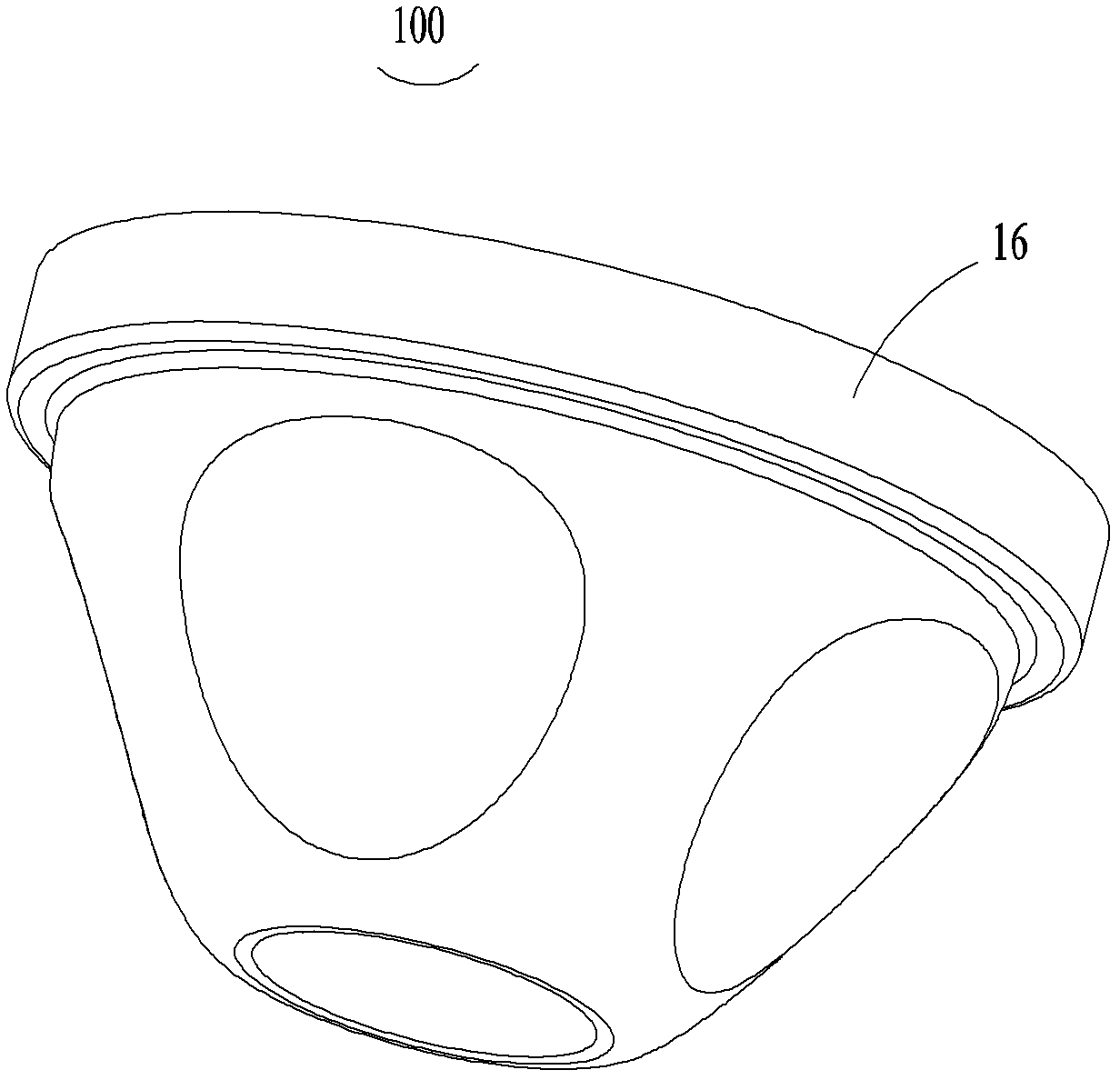
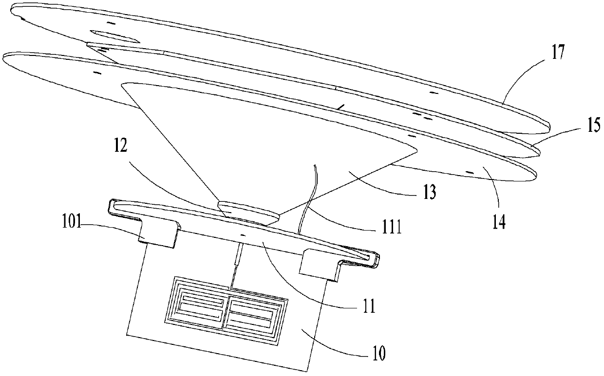
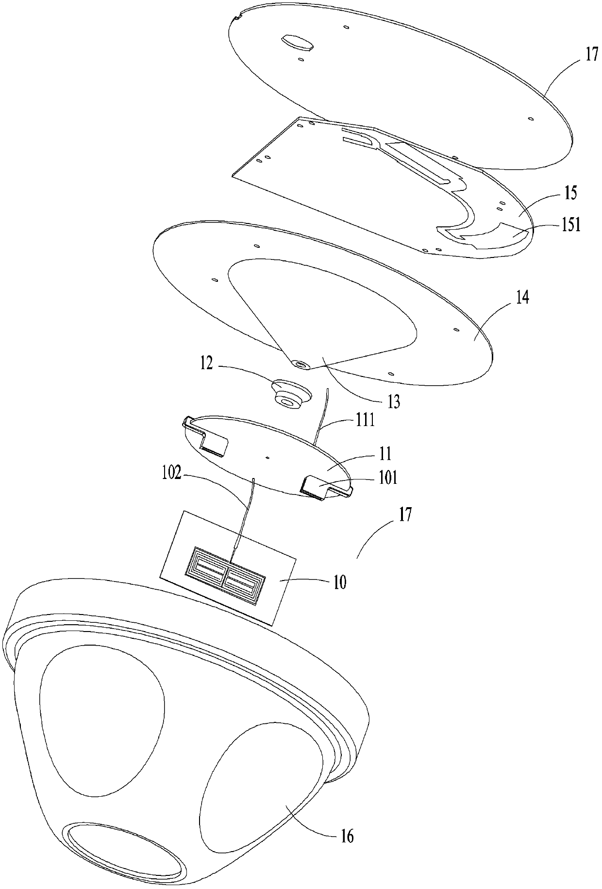
[0022] see figure 1 , figure 2 with image 3 , figure 1 It is the overall appearance diagram of the ceiling antenna of the present invention, figure 2 for figure 1 Schematic diagram of the structure after removing the lower shell, spacers and studs, figure 1 shows the overall appearance of the ceiling antenna 100 of the present invention, mainly the lower shell 16, see the specific structure figure 2 with image 3 . figure 2 an...


PUM


Abstract

The invention provides a ceiling-mounted antenna which comprises a PCB, a first radiation portion, a first signal transmission line, a first reflection portion and a second reflection portion. One end of the second reflection portion is fixedly connected with the first radiation portion, the other end of the second reflection portion is fixedly connected with the first reflection portion, the first reflection portion is fixedly installed on the PCB, and the first radiation portion is connected to the PCB through the first signal transmission line. According to the ceiling-mounted antenna, due to the structural design of the first radiation portion, the integral size is reduced, signal processing capacity of the ceiling-mounted antenna is improved, the signal use ratio of a signal source is improved through application of the reflection portions, and the ceiling-mounted antenna is simple in structure and convenient to install, and cannot influence indoor decoration.

Description

technical field [0001] The invention belongs to the field of communication equipment, and in particular relates to a ceiling-absorbing antenna. Background technique [0002] The indoor ceiling antenna is an antenna used for indoor signal coverage of wireless communication. It is generally installed on the ceiling to provide wireless signal coverage for an area with a radius of tens of meters centered on it. Outdoor signal coverage uses plate antennas with high power, strong signal, and long coverage; and indoor coverage, such as venues, hotels, office buildings, movie theaters, residential buildings, etc., needs to be covered by indoor distributed systems, so ceiling mounts are used. The antenna has a beautiful appearance and does not affect the interior decoration. [0003] The working frequency band of the traditional ceiling antenna is 800MHz-2500MHz, so according to the conventional antenna design principle, its height is about 80mm-100mm. In some indoor occasions, it ...

Claims


Application Information

Patent Timeline
Patent Type & Authority Patents(China)
IPC IPC(8): H01Q19/10H01Q1/38H01Q21/00
Inventor 刘若鹏徐冠雄邓存喜方能辉
Owner KUANG CHI INST OF ADVANCED TECH
Why Eureka
Try Eureka