

Vehicle-mounted mobile phone bracket
A technology for car mobile phones and mobile phone brackets, which is applied to vehicle parts, phone structure, transportation and packaging, etc., can solve problems such as damage, troublesome access, and mobile phone falling, so as to improve friction, clean friction, and facilitate handling. the effect
- Summary
- Abstract
- Description
- Claims
- Application Information
AI Technical Summary
Problems solved by technology
Method used
Image

Examples
Embodiment Construction
[0017] Further description will be given below in conjunction with the accompanying drawings
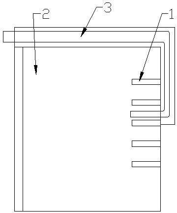
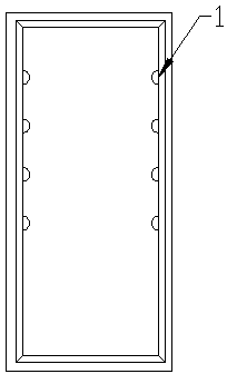
[0018] Such as Figure 1~3 As shown, a vehicle-mounted mobile phone bracket, the mobile phone bracket includes a shell 2, an anti-slip strip 1, the shell 2 is a cuboid box body, one side of the shell 2 is open, and the opening of the shell 2 shown is opposite On one surface, several anti-slip strips 1 are arranged on the four adjacent surfaces thereof, and the anti-slip strips 1 are perpendicular to a surface opposite to the opening of the casing 2, and the casing 2 is installed in the center console of the vehicle.
[0019] The inner wall surface of the shell 2 is covered with flocking cloth;
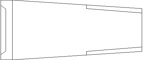
[0020] The shell 2 is a shrinking structure inwardly from the opening;
[0021] The shell 2 is made of engineering plastics;
[0022] A push rod 3 is also provided outside the housing 2, the push rod is made of flexible material, one end of the push rod 3 protrudes to the open end face of ...
PUM
 Abstract
Description
Claims
Application Information