Rebar loading and unloading device

A technology of loading and unloading devices and steel bars, applied in the directions of loading/unloading, transportation and packaging, conveyors, etc., which can solve the problems of single work object and high cost

Inactive Publication Date: 2020-10-23
杜圣秀
View PDF1 Cites 0 Cited by
  • Summary
  • Abstract
  • Description
  • Claims
  • Application Information

AI Technical Summary

Problems solved by technology

However, in the early stage of the device, a crane is required to place the steel bars on the material rack, and only the steel bar trays can be loaded and unloaded. high

Method used


Image

  • Rebar loading and unloading device
  • Rebar loading and unloading device
  • Rebar loading and unloading device

Examples


Embodiment 1

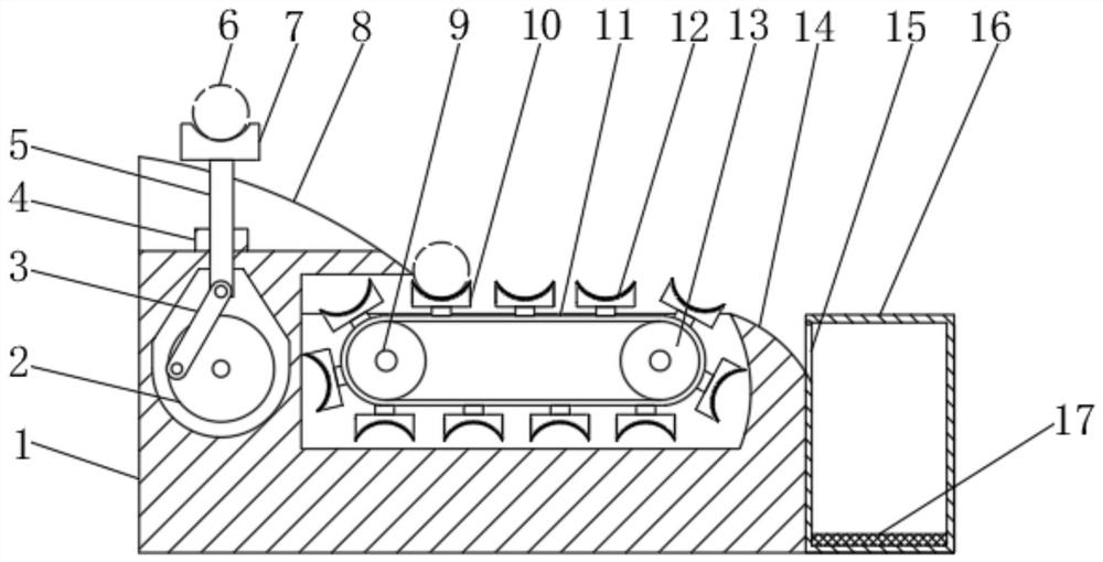
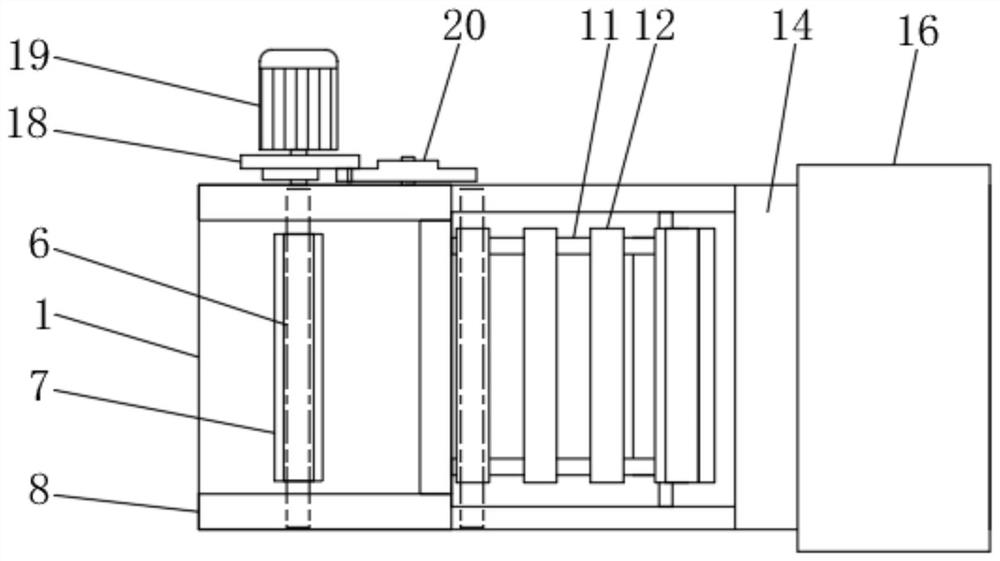
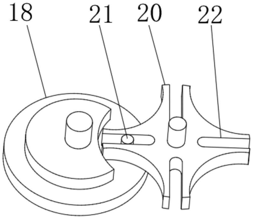
[0026] Embodiment one: refer to Figure 1~4 , in an embodiment of the present invention, a steel bar loading and unloading device includes a base 1, a motor 19 is arranged at the rear end of the base 1 to provide a power source, the output shaft end of the motor 19 is connected to a turntable 2, and the turntable 2 is arranged inside the base 1 In operation, the front end of the turntable 2 is rotatably connected to the connecting rod 3, and the connecting rod 3 is rotatably connected to the support column 5, and the outer end of the support column 5 passing through the base 1 is fixedly connected to the tray 7, and the steel bar body 6 is placed on the tray 7. When the tray 7 reciprocates up and down, the continuous loading and unloading of the steel bar body 6 is realized. The front and rear positions of the upper end of the base 1 are provided with a first slope belt 8, and the slope of the first slope belt 8 is gentle, so as to avoid the steel bar body 6 from rolling down. ...

Embodiment 2

[0035]Embodiment 2: This invention also provides another embodiment, which is improved on the basis of the above embodiment. The right end of the base 1 is provided with a second slope belt 14, so as to realize the adjustment of the steel bar body 6 Another buffer, the lower end of the second slope belt 14 is facing the entrance 15, and the whole device realizes that the delivery of the steel bar body 6 is stable.

[0036] In summary, when the invention works, the motor 19 is turned on, the same motor 19 provides power, and the turntable 2 is used to drive the connecting rod 3 to rotate. Drive the tray 7 to reciprocate up and down. When moving down, the tray 7 moves into the gap between the first slope belts 8, and the steel bar body 6 is supported by the first slope belt 8 and leaves the tray 7 and slides down along the first slope belt 8. Into the conveying tray 10, with the help of the cushion 12 to reduce the impact force, at the same time, the motor 19 drives the runner 1...


PUM


Abstract

The invention discloses a rebar loading and unloading device and relates to the field of buildings. The rebar loading and unloading device comprises a base, a motor is arranged at the rear end of thebase, and the output shaft end of the motor is connected with a rotary disc. The front end of the rotary disc is rotationally connected with a connecting rod, and the connecting rod is rotationally connected with a supporting column. The outer end of the supporting column penetrating through the base is fixedly connected with tray, and a rebar body is arranged on the tray. First slope zones are arranged on the front portion and the rear portion of the upper end of the base, a rotary wheel is arranged on an output shaft of the motor, and the front end of the rotary wheel is fixedly connected with a limiting pin. The limiting pin is movably connected with a groove wheel through a limiting groove. The rotary disc, the connecting rod and the supporting column rotate to achieve the reciprocating motion of the tray; when the tray moves downwards, the rebar body is separated from the tray and falls into conveying discs along the first slope zones, a conveying belt intermittently conveys the rebar, the rebar enters a collecting box through a second slope zone, and automatic loading and unloading of the rebar are effectively achieved; and the loading and unloading cost is low, input of large equipment is reduced, loading and unloading are orderly, and the subsequent finishing amount is reduced.

Description

technical field [0001] The invention relates to the construction field, in particular to a steel bar loading and unloading device. Background technique [0002] Steel bar refers to the steel used for reinforced concrete and prestressed reinforced concrete. Its cross section is circular, sometimes square with rounded corners, and it is the most common building material in the field of construction. Including plain round bars, ribbed bars, twisted bars. Steel bars for reinforced concrete refer to the straight or coiled steel used for reinforced concrete reinforcement. Its shape is divided into two types: smooth round steel bar and deformed steel bar. The delivery state is straight bar and coiled round. Steel bars mainly bear tensile stress in concrete. Light round steel bars are actually small round bars and discs of ordinary low carbon steel. Deformed bars are ribbed bars on the surface, usually with 2 longitudinal ribs and transverse ribs evenly distributed along the leng...

Claims


Application Information

Patent Timeline
Patent Type & Authority Applications(China)
IPC IPC(8): B65G15/58B65G15/42B65G65/32B65G17/12
CPCB65G15/42B65G15/58B65G17/12B65G65/32
Inventor 杜圣秀
Owner 杜圣秀
Why Eureka
Try Eureka