Magnetic-force-driven multi-stage pump with double rotors

A magnetic drive, dual-rotor technology, applied in the field of multi-stage pumps, can solve the problems of difficulty in ensuring the accuracy of the pump shaft, difficulty in installation and maintenance, and affecting the balanced operation of the pump, achieving reduced operating vibration, convenient disassembly and maintenance, and simple structure Effect

Inactive Publication Date: 2014-03-05
丹东克隆先锋泵业有限公司
View PDF6 Cites 2 Cited by
  • Summary
  • Abstract
  • Description
  • Claims
  • Application Information

AI Technical Summary

Problems solved by technology

For multistage pumps with higher stages, such as 16 or even higher stage multistage pumps, the pump shaft is too long, it is difficult to guarantee the accuracy requirements for the processing of the pump shaft, and the precision of the pump shaft is not enough, which will seriously affect the pump shaft. The balanced operation reduces the service life, and it is difficult to install and maintain

Method used


Image

  • Magnetic-force-driven multi-stage pump with double rotors

Examples


Embodiment Construction

[0008] specific implementation

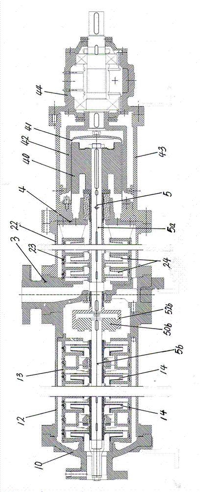
[0009] The present invention retains the basic structure of the multistage pump , The pump shaft is divided into the active pump shaft 5a and the driven pump shaft 5b. The front and rear ends of the active pump shaft 5a are respectively mounted on the worm disk 3 at the liquid outlet and the bearing housing end plate 4 at the rear end of the rear pump chamber 22 through bearings. Above, the front and rear ends of the driven pump shaft 5b are respectively mounted on the front deflector frame 13 in the front pump chamber 12 through bearings, and the driven outer magnetic rotors are fixedly connected to the front and rear ends of the active pump shaft 5a. 52b and the active inner magnetic rotor 40 are fixedly connected on the rear shaft end of the driven pump shaft 5b. The driven inner magnetic rotor 50b cooperates with the driven outer magnetic rotor 52b on the front end of the active pump shaft 5a. The active inner magnetic rotor 40 at t...


PUM


Abstract

The invention relates to a magnetic-force-driven multi-stage pump with double rotors. The magnetic-force-driven multi-stage pump with the double rotors comprises a liquid feeding pump opening cap (10), a front pump cavity barrel (12), a front flow guiding plate rack (13), a front multi-stage blade (14), a liquid outlet worm plate (3), a rear pump cavity barrel (22), a rear flow guiding plate rack (23), a rear multi-stage blade (24), a bearing block end plate (4), an inner magnetic rotor (40), a spacer sleeve (41), an outer magnetic rotor (42), a connecting rack (43), a bearing frame (44) and a pump shaft (5). The magnetic-force-driven multi-stage pump is characterized in that the pump shaft (5) consists of a driving pump shaft (5a) and a driven pump shaft (5b); and a driven outer magnetic rotor (52b) is arranged at the front end of the driving pump shaft (5a) and is matched with a driven inner magnetic rotor (50b) arranged at the rear end of the driven pump shaft (5b), so that the driven pump shaft (5b) is driven to rotate. The magnetic-force-driven multi-stage pump is simple in structure; the processing difficulty is greatly reduced; the running balance of the pump is improved; the service life of the pump is prolonged; and moreover, the magnetic-force-driven multi-stage pump which is assembled in a split manner is convenient to mount, dismount and repair.

Description

technical field [0001] The invention relates to a multistage pump, in particular to a multistage centrifugal vane (wheel) series magnetic drive pump. Background technique [0002] A pump with two or more impellers on one shaft is called a multistage pump. Multistage pumps are mainly used in occasions with small flow and high head. [0003] The difficulty in the design of multistage pumps lies in the control of the axial force and the machining accuracy of the pump shaft. Multistage pumps can often use circulation pipes and back-to-back arrangement of blades to control axial force. The pump shaft length of 4-6 stage multistage pumps is slightly longer than that of ordinary pumps, but the processing can basically guarantee the accuracy requirements. . For multistage pumps with higher stages, such as 16 or even higher stage multistage pumps, the pump shaft is too long, it is difficult to guarantee the accuracy requirements for the processing of the pump shaft, and the precis...

Claims


Application Information

Patent Timeline
Patent Type & Authority Applications(China)
IPC IPC(8): F04D29/043F04D1/08F04D13/02
Inventor 赵强杨德乾柴鹏举马伟利王晓龙王廷波王勐冷旭何德贵许斌滕朋李景涛窦文强佟有德
Owner 丹东克隆先锋泵业有限公司
Why Eureka
Try Eureka