punching die

A mold and punching technology, applied in the direction of perforating tools, forming tools, manufacturing tools, etc., to achieve the effect of saving manufacturing costs

Active Publication Date: 2016-04-06
廊坊事达同泰汽车零部件有限公司
View PDF6 Cites 2 Cited by
  • Summary
  • Abstract
  • Description
  • Claims
  • Application Information

AI Technical Summary

Problems solved by technology

However, the existing punching dies also need a special flanging die to flang the workpiece after the punching is completed.

Method used


Image

  • punching die

Examples


Embodiment Construction

[0013] The specific embodiments of the present invention will be described in further detail below in conjunction with the drawings and embodiments. The following examples are used to illustrate the present invention, but not to limit the scope of the present invention.

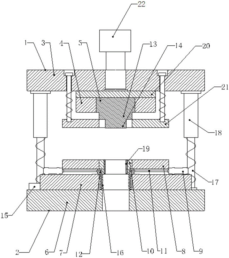
[0014] Such as figure 1 As shown, the punching die of the present invention includes an upper die set 1 and a lower die set 2. The upper die set is fixedly connected to an external driving device 22, wherein the upper die set includes an upper die base 3, a punch fixing plate 4 and Punch 5, the punch fixing plate is installed on the lower surface of the upper mold base, the punch is set on the punch fixing plate, the lower module includes the lower mold base 6, and the lower pad 7 installed on the upper surface of the lower mold base is installed on the lower surface. The concave mold 8 on the upper surface of the backing plate also includes a cylinder 9 and a concave mold insert 10. The cylinder is installed o...


PUM


Abstract

The invention discloses a punching die and relates to the technical field of stamping dies. The punching die can be used for punching and flanging and has multiple functions. The punching die comprises an upper die set and a lower die set. The upper die set is fixedly connected with an external driving device. The upper die set comprises an upper die base and a punch. The lower die set comprises a lower die base, a female die, air cylinders and a female die internal insert. The air cylinders are arranged on the outer sidewall of the female die in the horizontal direction. Grooves or first through holes are formed in the positions, corresponding to the air cylinders, of the female die in the horizontal direction. The top ends of piston rods are connected with ejecting blocks for limiting the female die internal insert to move downwards. The lower portion of the female die internal insert is connected with an elastic device. The punch comprises a punch body matched with a die cavity of the female die. The lower end of the punch body protrudes out of the lower surface of the punch and is provided with a punch insertion block. The punching die further comprises a control device which is used for controlling stretching out or drawing back of the piston rods of the air cylinders.

Description

Technical field [0001] The invention relates to the technical field of stamping dies, in particular to a punching die. Background technique [0002] As we all know, the punching die is a punching die used to punch the workpiece. The existing punching die includes an upper die set and a lower die set, wherein the upper die set includes an upper die base and a punch. The lower mold base includes a lower mold base and a concave mold. When working, the upper die seat moves downward to drive the punch to punch the workpiece placed on the upper surface of the concave die, thereby completing the punching. However, the existing punching die needs a special flanging die to flange the workpiece after the punching is completed. Summary of the invention [0003] In order to solve the above technical problems, the present invention provides a punching die capable of punching and flanging. [0004] The punching die of the present invention includes an upper die set and a lower die set. The up...

Claims


Application Information

Patent Timeline
Patent Type & Authority Patents(China)
IPC IPC(8): B21D37/10B21D28/34
Inventor 张金斌
Owner 廊坊事达同泰汽车零部件有限公司
Why Eureka
Try Eureka