A panel punching and shaping device

A panel and stamping table technology, applied in the field of mechanical processing and manufacturing, can solve the problem that the stamping mechanism cannot punch holes at the same time, and achieve the effects of achieving bending plasticity, improving processing efficiency, and reducing processing costs

Active Publication Date: 2020-05-12
SHANDONG STREET MOBILE SHOP NEW ENERGY TECH CO LTD
View PDF5 Cites 0 Cited by
  • Summary
  • Abstract
  • Description
  • Claims
  • Application Information

AI Technical Summary

Problems solved by technology

[0004] The present invention intends to provide a panel stamping and shaping device to solve the problem that the existing stamping mechanism cannot punch holes at the same time

Method used


Image

  • A panel punching and shaping device
  • A panel punching and shaping device
  • A panel punching and shaping device

Examples


Embodiment Construction

[0023] The following is further described in detail through specific implementation methods:

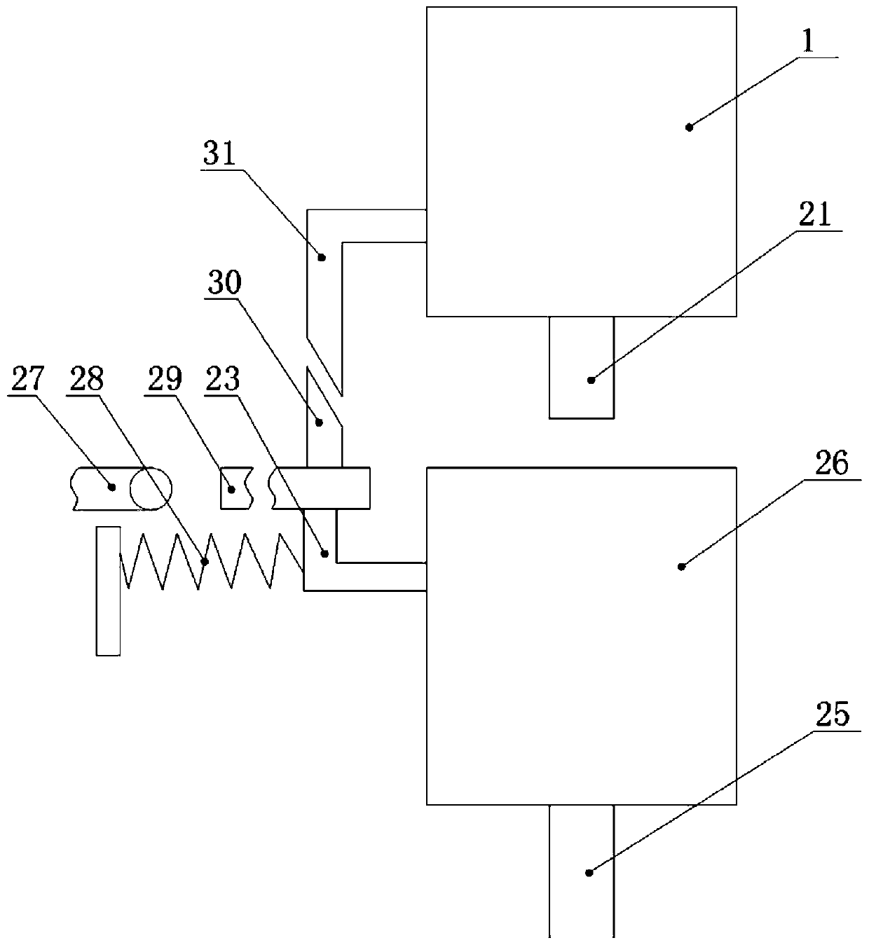
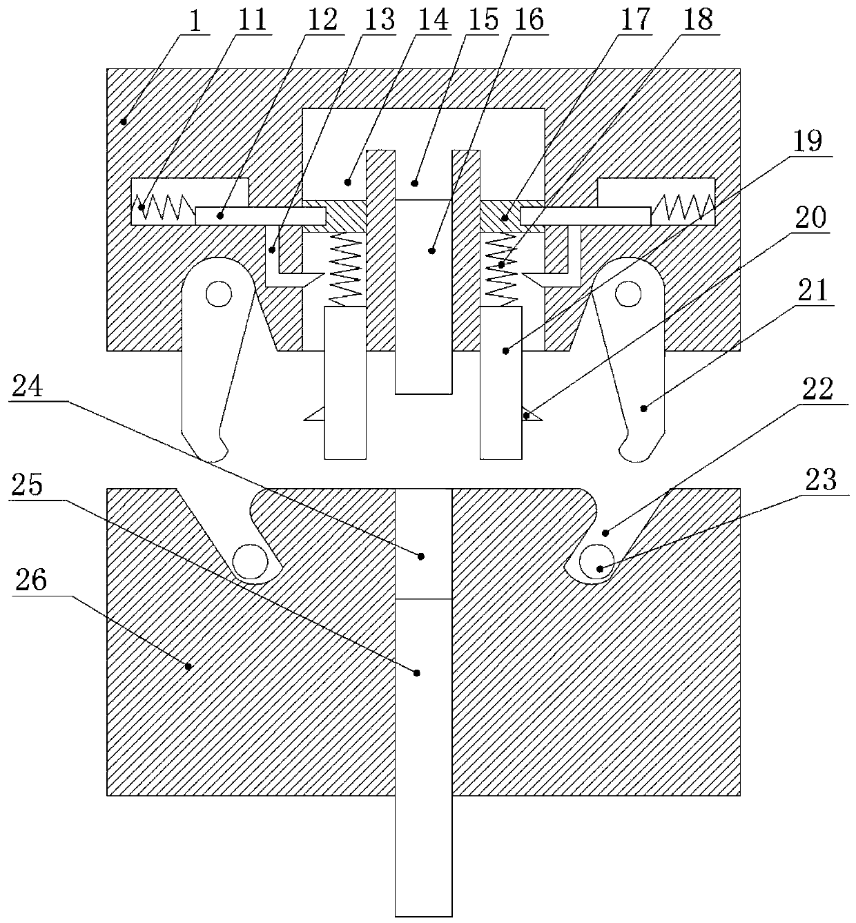
[0024] The reference signs in the accompanying drawings of the description include: punch 1, third spring 11, latch 12, third wedge rod 13, first liquid storage tube 14, second liquid storage tube 15, punching knife 16, piston 17, First spring 18, pressing rod 19, wedge 20, jaw 21, groove 22, push rod 23, shape hole 24, ejector rod 25, stamping table 26, conveyor belt 27, second spring 28, loading plate 29, The first wedge bar 30 and the second wedge bar 31 .

[0025] Such as figure 1 As shown, a panel stamping and shaping device of the present invention includes a frame, on which a stamping table 26 is installed, and a mold groove 22 is symmetrically opened on the stamping table 26 with its center line as the center, and the outer side wall of the mold groove 22 forms inclined plane. A punching table 26 between the two grooves 22 is vertically provided with a mold hole 24 , and a...


PUM


Abstract

The invention relates to the field of machining and manufacturing, in particular to a panel stamping molding device which comprises a rack; the rack is provided with a stamping table; molding groovesare symmetrically formed in the stamping table; the side wall of the outer side of each molding groove forms an inclined surface; a molding hole is formed between the molding grooves; a stamping headis arranged above the stamping table; clamping jaws capable of being inserted into the molding grooves respectively are hinged to the stamping head and are provided with wedged surfaces matched with the corresponding inclined surfaces respectively; first liquid storage pipes are symmetrically arranged between the clamping jaws and are internally provided with pistons in a sliding manner respectively; a pressure rod is arranged below each piston in the sliding manner; a first spring is connected between each pressure rod and the corresponding piston; the stamping head is provided with a limiting mechanism used for fixing the pistons; a second liquid storage pipe is communicated between the first liquid storage pipes and is internally provided with a punching cutter capable of being insertedinto the corresponding molding hole in the sliding manner; and the stamping head is internally provided with a drive mechanism. The panel stamping molding device solves the problem that the existingstamping mechanism cannot perform stamping at the same time.

Description

technical field [0001] The invention relates to the field of mechanical processing and manufacturing, in particular to a panel punching and shaping device. Background technique [0002] Panel is one of the common parts in our daily life. It is widely used in electrical appliances, machinery and other fields, such as refrigerator panels, switch panels, air conditioner panels, etc. Panels need to go through cutting, stamping, punching, grinding, painting and other processes in the process of processing. [0003] Existing panel stamping is generally operated by a stamping mechanism, but the existing stamping mechanism has the following defects: 1. It can only simply stamp the panel. When the panel needs to be punched, it needs to use a punching device to operate. It increases the processing cost and reduces the overall processing efficiency of the panel; 2. The edge of the panel cannot be bent and plasticized, and a special device needs to be used for operation, which results ...

Claims


Application Information

Patent Timeline
Patent Type & Authority Patents(China)
IPC IPC(8): B21D35/00B21D28/26B21D22/02B21D43/00
CPCB21D22/02B21D28/26B21D35/001B21D43/003
Inventor 熊强
Owner SHANDONG STREET MOBILE SHOP NEW ENERGY TECH CO LTD
Why Eureka
Try Eureka