
Intelligent automatic die adjusting mechanism based on oil press principle

A technology of automatic adjustment and hydraulic press, which is applied in the direction of presses, stamping machines, manufacturing tools, etc. It can solve the problems of stepless adjustment of screw adjustment accuracy, low precision of automatic mold adjustment of hydraulic presses, and screw breakage, so as to improve the quality of punching products , Improving the precision of die-cutting and improving the effect of uniformity

Inactive Publication Date: 2020-09-11
嘉兴久珥科技有限公司
View PDF6 Cites 0 Cited by
  • Summary
  • Abstract
  • Description
  • Claims
  • Application Information

AI Technical Summary

Problems solved by technology

[0003] However, the synchronous structure of the screw generally increases the rotational torque of the screw through the gear ratio during the transmission process, and then converts the rotation of the screw into the punching kinetic energy of the upper and lower dies through the rotational connection between the upper and lower dies and the screw. In use, when punching thicker or harder steel parts, the teeth on the surface of the screw are prone to broken teeth or the screw is broken due to high torque, and the adjustment accuracy of the screw is limited by the distance between the screw teeth and cannot be infinitely adjusted. , leading to low accuracy of automatic mold adjustment of the hydraulic press, and there are certain defects

Method used


Image

  • Intelligent automatic die adjusting mechanism based on oil press principle
  • Intelligent automatic die adjusting mechanism based on oil press principle
  • Intelligent automatic die adjusting mechanism based on oil press principle

Examples


Embodiment Construction

[0022] The technical solutions in the embodiments of the present invention will be clearly and completely described below in conjunction with the accompanying drawings in the embodiments of the present invention. Obviously, the described embodiments are only some of the embodiments of the present invention, not all of them. Based on the embodiments of the present invention, all other embodiments obtained by persons of ordinary skill in the art without creative work all belong to the protection scope of the present invention.

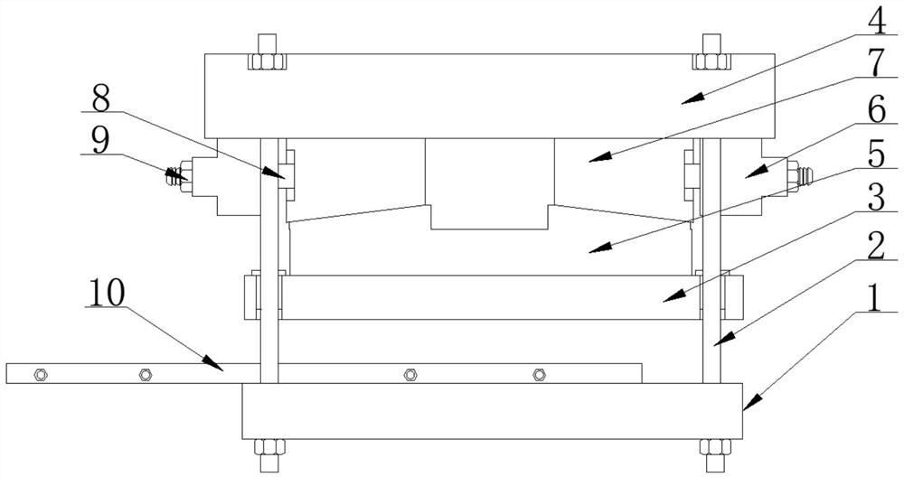
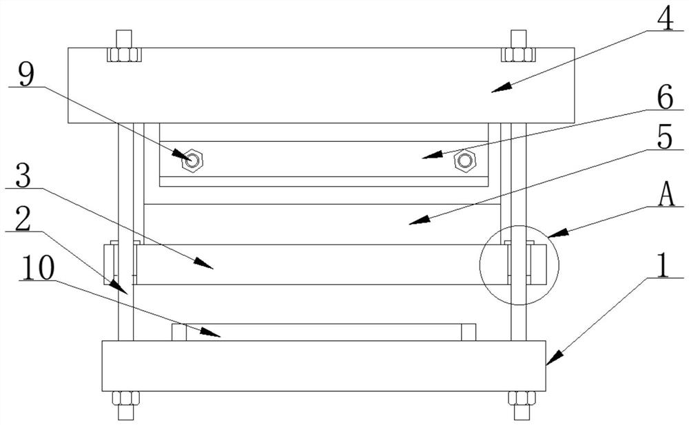
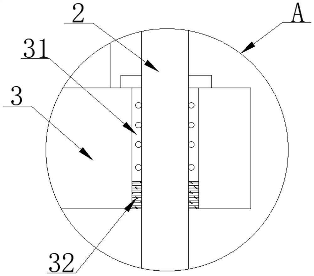
[0023] as attached Figure 1-5 The shown is an intelligent automatic mold adjustment mechanism based on the principle of a hydraulic press, including a punching base plate 1, a linear guide rod 2, a punching die 3 and a feeding mechanism 10. The end of the feeding mechanism 10 is located at the end of the punching base plate 1. On the top surface, the surface of the linear guide rod 2 is provided with a through hole and is sleeved on the surface of the l...


PUM


Abstract

The invention discloses an intelligent automatic die adjusting mechanism based on an oil press principle, and particularly relates to the field of machining. The intelligent automatic die adjusting mechanism based on the oil press principle comprises a punching bottom plate, a linear guide rod, a punching die and a feeding mechanism, a fixed seat is installed at the top end of the linear guide rod, a tapered wedge moving block is slidably connected to the bottom face of the fixed seat, and a hydraulic jacking mechanism is installed on the bottom face of the fixed seat; and the output end of the hydraulic jacking mechanism is connected with a jacking rod, the top face of the punching die is connected with a tapered wedge pressing die in a clamped mode, and the input end of the hydraulic jacking mechanism is connected with a hydraulic driving mechanism. According to the intelligent automatic die adjusting mechanism, a tapered wedge lifting mechanism is arranged, the tapered wedge movingblock transversely moves on the surface of the tapered wedge pressing die, and the transverse jacking force driven hydraulically is converted into lifting power of the punching die through the taperedwedge lifting mechanism, so that punching of a workpiece is achieved; and compared with a traditional lead screw lifting structure, the tapered wedge lifting mechanism is more stable and higher in structural strength, the tapered wedge lifting mechanism is suitable for punching high-hardness workpieces, the fault rate is low, and the service life is greatly prolonged.

Description

technical field [0001] The present invention relates to the technical field of mechanical processing, and more specifically, the present invention is an intelligent automatic mold adjustment mechanism based on the principle of hydraulic press. Background technique [0002] At present, hydraulic presses include punching for conventional hardware and punching for non-metallic diaphragms after special modification. Next, calculate the linear relationship between the punching depth and the rotation speed of the mold-adjusting motor. The mold-adjusting motor realizes automatic mold adjustment, and the transmission structure controls the four-corner screws to perform synchronous lifting to realize synchronous die-cutting. [0003] However, the synchronous structure of the screw generally increases the rotational torque of the screw through the gear ratio during the transmission process, and then converts the rotation of the screw into the punching kinetic energy of the upper and l...

Claims


Application Information

Patent Timeline
IPC IPC(8): B21D28/02B21D28/14B30B1/32B30B15/16B30B15/24
CPCB21D28/002B21D28/02B21D28/14B30B1/32B30B15/166B30B15/24
Inventor 吕金坤吕燕
Owner 嘉兴久珥科技有限公司
Learn More