Gate drive circuit

A gate drive circuit and drive voltage technology, applied in the direction of instruments, static indicators, etc., can solve the problems of unstable drive voltage, affecting the drive capability of shift registers, etc., and achieve the effect of high drive voltage and good drive capability

Active Publication Date: 2016-05-11
AU OPTRONICS CORP
View PDF4 Cites 0 Cited by
  • Summary
  • Abstract
  • Description
  • Claims
  • Application Information

AI Technical Summary

Problems solved by technology

However, the driving voltage stored in the energy storage unit of the existing shift register is not only used to generate the gate signal, but also used to generate other control signals. Therefore, the energy storage unit of the existing shift register The stored driving voltage is relatively unstable, which in turn affects the driving capability of the existing shift register

Method used


Image

  • Gate drive circuit
  • Gate drive circuit
  • Gate drive circuit

Examples


Embodiment Construction

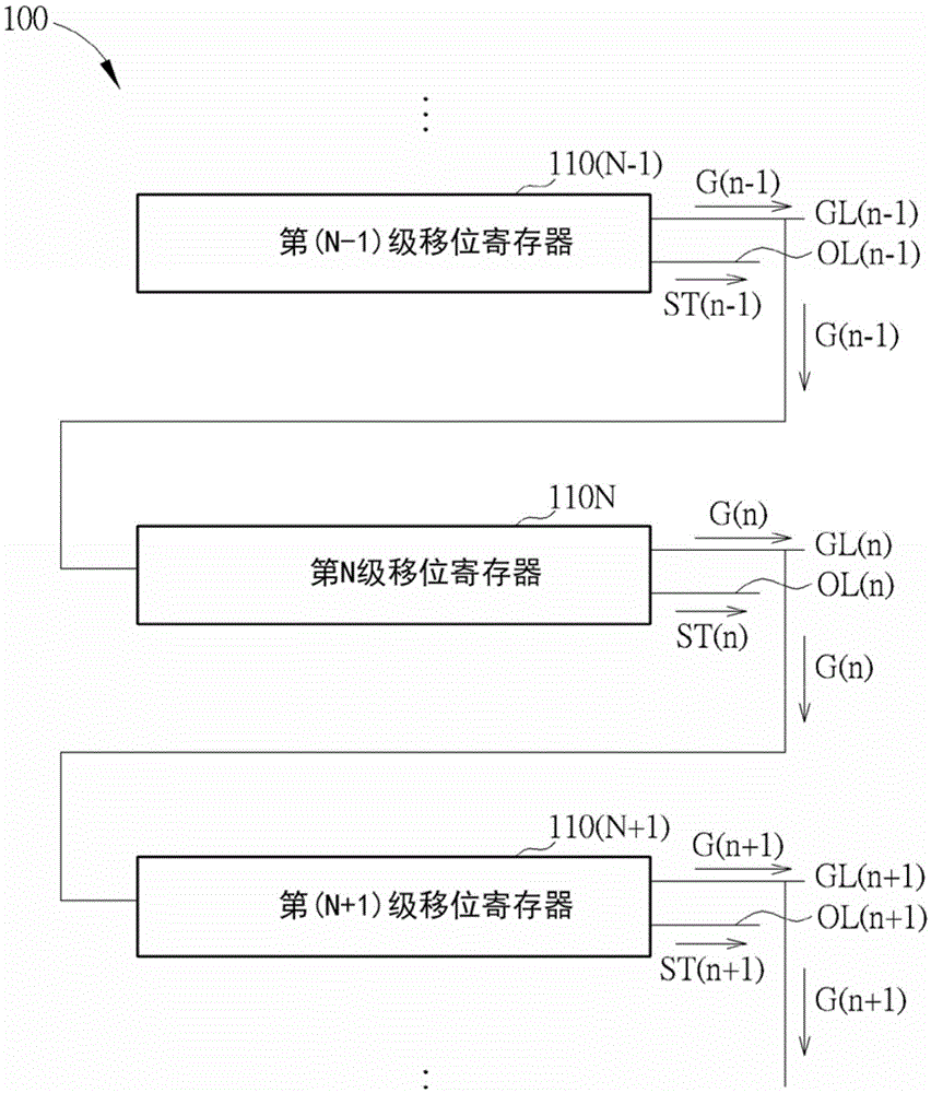
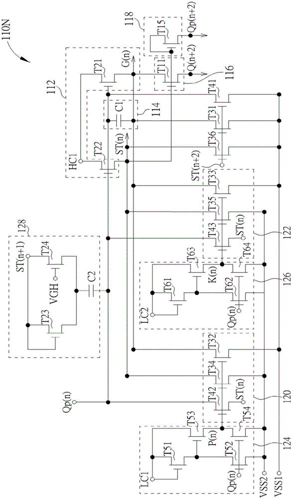
[0037] Please also refer to figure 1 and figure 2 , figure 1 It is a schematic diagram of the gate drive circuit of the present invention, figure 2 for figure 1 Schematic diagram of the Nth-stage shift register of the gate drive circuit. As shown in the figure, the gate drive circuit 100 includes a multi-stage shift register. For the convenience of illustration, the gate drive circuit 100 only shows the (N-1)th stage shift register 110 (N-1), the N-stage shift register Register 110N and (N+1) stage shift register 110 (N+1), wherein only the N stage shift register 110N is in figure 2 The internal structure is shown in , and the shift registers of other stages are similar to the shift register 110N of the Nth stage, so no further description is given. N is a positive integer greater than 1. The (N-1)th stage shift register 110(N-1) is used to provide the transfer signal ST(n-1) and the gate signal G(n-1), and the Nth stage shift register 110N is used to provide the tran...


PUM


Abstract

The invention discloses a grid electrode driving circuit. An N stage shifting register includes a pull-up unit used for pulling a first transmission signal of an output line and a first grid electrode signal of the grid line to a high level voltage based on driving voltage and high-frequency time-pulse signal. An energy storage unit is used for providing the driving voltage. The first driving unit is used for executing a charging program on an energy storage unit of the rear-stage shifting register based on the first transmission signal and the first grid electrode signal. The second drive unit is used for providing a pull-down signal to the rear-stage shifting register according to the first transmission signal. The first pull-down unit is used for pulling down the driving voltage, the first grid electrode signal and the first transmission signal based on the first control signal. And a first control unit is used for producing the first control signal based on the first low-frequency time-pulse signal and the pull-down control signal provided by the front-stage shifting register.

Description

technical field [0001] The invention relates to a gate drive circuit, in particular to a gate drive circuit capable of improving driving capability. Background technique [0002] Generally speaking, a liquid crystal display panel includes a plurality of pixels, a gate driving circuit and a source driving circuit. The source driving circuit is used for writing data signals to the turned-on pixels. The gate driving circuit includes a multi-stage shift register, which is used to provide multiple gate signals to control the on and off of the pixels. In the operation of the shift register, the driving voltage stored in the energy storage unit of the shift register is related to the driving capability of the shift register. When the driving voltage is higher and more stable, the gate signal output by the shift register has better driving performance. ability. However, the driving voltage stored in the energy storage unit of the existing shift register is not only used to genera...

Claims


Application Information

Patent Timeline
Patent Type & Authority Patents(China)
IPC IPC(8): G09G3/36
Inventor 詹秉燏洪凯尉陈勇志张晴惠
Owner AU OPTRONICS CORP
Why Eureka
Try Eureka