Al technical title is built by PatSnap Al team. It summarizes the technical point description of the patent document.
A stabilized platform, heavy-duty technology, applied in the structural design of stabilized platforms, shipborne heavy-duty stabilized platforms, can solve the problems of small load capacity, inability to achieve stability, high delay, etc., to improve stability accuracy, improve structural strength, and load powerful effect
Active Publication Date: 2014-04-30
HEBEI HANGUANG HEAVY IND
View PDF4 Cites 9 Cited by
Summary
Abstract
Description
Claims
Application Information
AI Technical Summary
This helps you quickly interpret patents by identifying the three key elements:
Problems solved by technology
Method used
Benefits of technology
Problems solved by technology
[0002] The stability of the existing stable platform is mainly achieved by using the gyroscope as a sensor to sense the speed of the rotating shaft, thereby controlling the motor to perform reverse compensation motion to achieve stability. There are two types of existing stable platforms, one is to use a torque motor as a drive to achieve Stable, the platform is mostly suitable for a load of about 5-20kg. Although the stable platform is small and light, its load is too small for large transport ships to play a stable role, and when the torque motor is used as the drive of the stable platform, The center of gravity of the load must be controlled within the center of slewing, which is difficult to control and has a small load capacity; the other is a stable platform suitable for large equipment, mainly driven by hydraulic devices, and suitable for loads above 500kg
However, the use of hydraulic drive requires a hydraulic source. Generally, the hydraulic source equipment is relatively large in size, which is not suitable for the stable platform of general medium-sized equipment, and the delay is relatively high.
Method used
Image
Click on the blue label to locate the original text in one second.
Reading with bidirectional positioning of images and text.
Examples
Embodiment Construction
[0032] The specific implementation of the present invention will be further described below in conjunction with the accompanying drawings and examples. The following examples are only used to illustrate the technical solutions of the present invention more clearly, but not to limit the protection scope of the present invention.
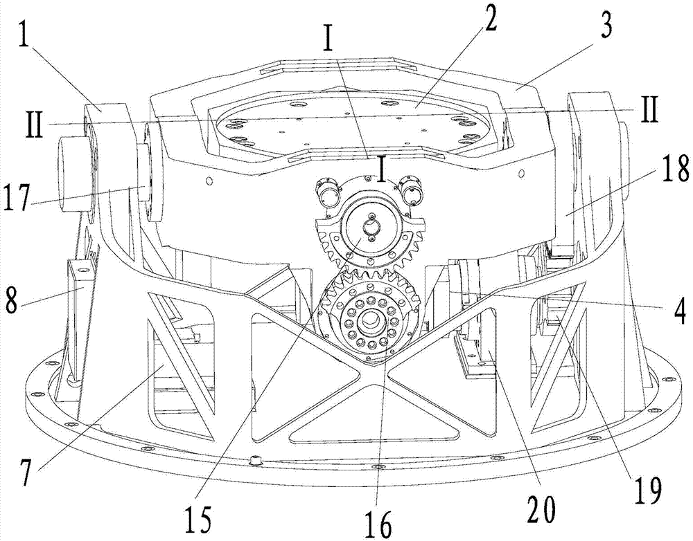
[0033] Such as Figure 1 to Figure 9 As shown, the technical solution of the present invention is a ship-borne heavy-duty stable platform, including a main bracket 1, an installation platform 2, an inner frame 3, a roll servo reduction motor 4, a servo control box 5, and a pitch servo reduction motor 6 , gyro board 7, gyro A8, gyro B9, angle sensor A10, angle sensor B11, inclination sensor 12, inner ring shaft A13, inner ring shaft B14, inner ring gear 15, inner ring servo motor gear 16, outer ring shaft 17, Gear shaft 18, outer ring servo motor gear 19, motor bracket 20;
[0034] Wherein, the main bracket 1 includes a chassis 1-1 and a support ring;...
PUM
Abstract
The invention belongs to the field of machinery manufacturing, and relates to a ship-based heavy stabilizing platform, in particular to structural design of stabilizing platforms with the load being more than 250 kg. The ship-based heavy stabilizing platform comprises a main support, an installation platform, an inner frame, a rolling servo gear motor, a servo control box, a pitching servo gear motor, a spinning top plate, a spinning top A, a spinning top B, an angle sensor A, an angle sensor B, an inclination angle sensor, an inner ring shaft A, an inner ring shaft B, an inner ring gear, an inner ring servo motor gear, an outer ring shaft, a gear shaft, an outer ring servo motor gear and a motor support. The ship-based heavy stabilizing platform has the advantages of being high in bearing capacity, high in stabilizing precision and quick in response. The ship-based heavy stabilizing platform can realize stabilization without a counter weight. Due to the fact that the ship-based heavy stabilizing platform is provided with the inclination angle sensor, drift generated by the spinning tops can be corrected in appropriate time, and the stabilizing precision can be improved.
Description
technical field [0001] The patent of the invention relates to a ship-borne heavy-duty stable platform, in particular to a structural design of a stable platform with a load of more than 250kg, which belongs to the field of machinery manufacturing. Background technique [0002] The stability of the existing stable platform is mainly achieved by using the gyroscope as a sensor to sense the speed of the rotating shaft, thereby controlling the motor to perform reverse compensation motion to achieve stability. There are two types of existing stable platforms, one is to use a torque motor as a drive to achieve Stable, the platform is mostly suitable for a load of about 5-20kg. Although the stable platform is small and light, its load is too small for large transport ships to play a stable role, and when the torque motor is used as the drive of the stable platform, The center of gravity of the load must be controlled within the center of slewing, which is difficult to control and h...
Claims
Application Information
Patent Timeline
Application Date:The date an application was filed.
Publication Date:The date a patent or application was officially published.
First Publication Date:The earliest publication date of a patent with the same application number.
Issue Date:Publication date of the patent grant document.
PCT Entry Date:The Entry date of PCT National Phase.
Estimated Expiry Date:The statutory expiry date of a patent right according to the Patent Law, and it is the longest term of protection that the patent right can achieve without the termination of the patent right due to other reasons(Term extension factor has been taken into account ).
Invalid Date:Actual expiry date is based on effective date or publication date of legal transaction data of invalid patent.