
a hypnotizer
A technology of a hypnotic device and a shell is applied in the field of hypnotic devices, which can solve the problems of poor sound quality, simple structure, single hypnotic measures, etc., and achieve the effects of good hypnotic effect and good sound quality effect.
- Summary
- Abstract
- Description
- Claims
- Application Information
AI Technical Summary
Problems solved by technology
Method used
Image

Examples
Embodiment Construction
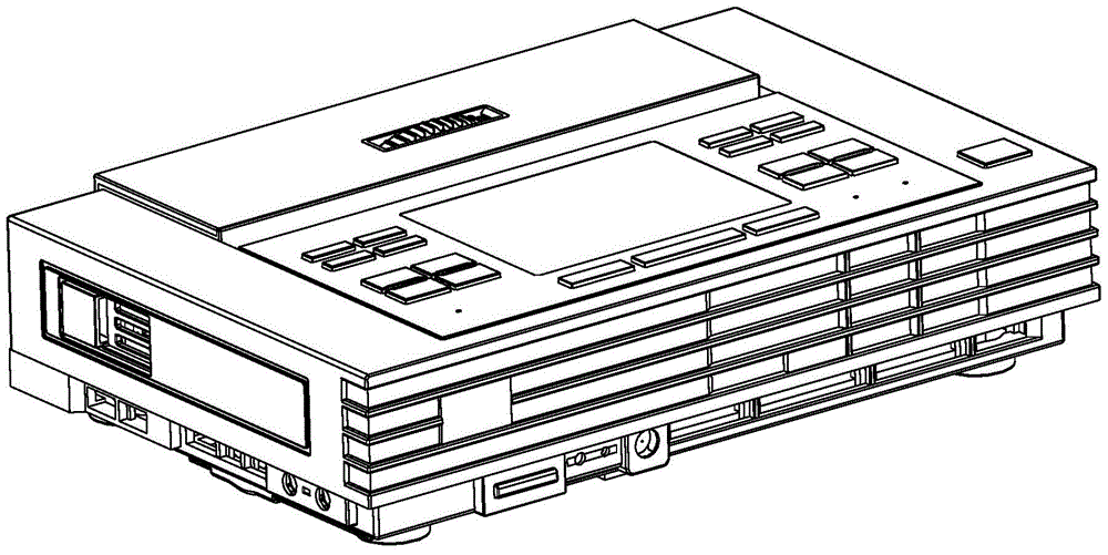
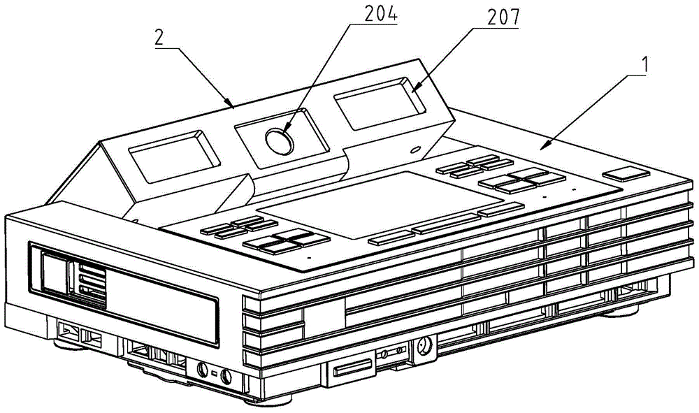
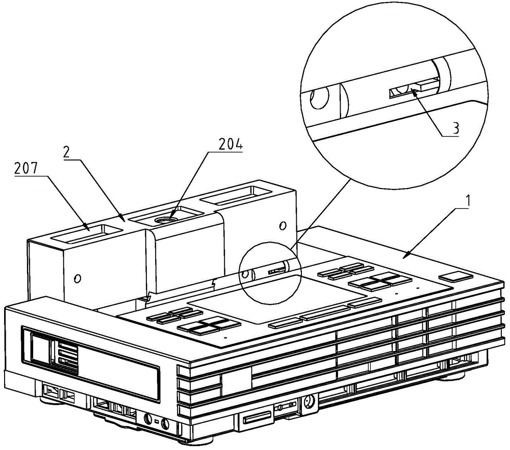
[0052] The structure of the hypnotizer of embodiment 1 of the present invention is as Figure 1 to Figure 14 shown.
[0053] Such as figure 1 Shown, the housing 1 of the hypnotizer body is U-shaped, and the projector housing 2 is buried in the groove of the U-shaped housing 1 when it is placed flat. The sidewalls 111 on both sides of the groove at the rear of the U-shaped housing 1 have hinged holes 112 . The rear parts of both sides of the projector housing 2 each include a hinge shaft hole 201 , and the hinge shaft 3 is inserted into the hinge shaft hole 201 . The compression spring 4 is also installed in the shaft connection hole 201 , between the rear end surface of the hinge shaft 3 and the bottom surface of the hinge shaft hole 201 .
[0054] The front end of the hinge shaft 3 is inserted into the hinge hole 112 of the side wall 111 of the housing, and the front end of the hinge shaft 3 has four positioning protrusions 301 uniformly distributed in the circumferential ...
PUM
 Abstract
Description
Claims
Application Information