Slicing mechanism for numerically controlled planer

A gantry planing and slicing technology, which is applied in the direction of planer, planer/slotting machine, metal processing equipment, etc., can solve the problems of affecting processing accuracy, poor stability of gantry planer, low efficiency, etc., to improve service life and reduce carrying load. Effect

Inactive Publication Date: 2014-05-14
徐州领君自动化设备有限公司
View PDF7 Cites 3 Cited by
  • Summary
  • Abstract
  • Description
  • Claims
  • Application Information

AI Technical Summary

Problems solved by technology

[0002] Gantry planer is a common equipment in the processing field. When the existing gantry planer processes parts, the beam needs to reciprocate up and down along the column. Because the weight of the beam is relatively large, it is easy to damage the rotating equipment during the up and down reciprocating movement. Moreover, the existing gantry planer The processing equipment is only installed on one side of the beam, and it is impossible to process multiple workpieces at the same time, which is inefficient; and the stability of the existing planer is poor, and the stability of the planer cannot be guaranteed, thus affecting the processing accuracy

Method used


Image

  • Slicing mechanism for numerically controlled planer
  • Slicing mechanism for numerically controlled planer
  • Slicing mechanism for numerically controlled planer

Examples


Embodiment

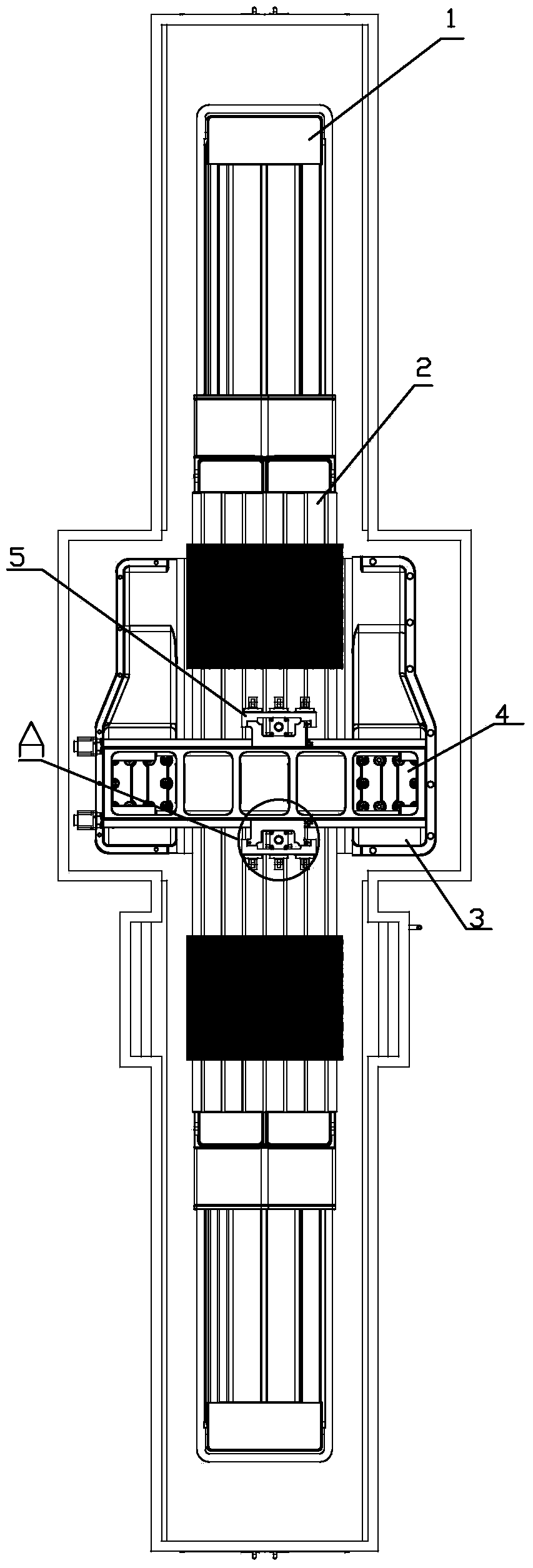
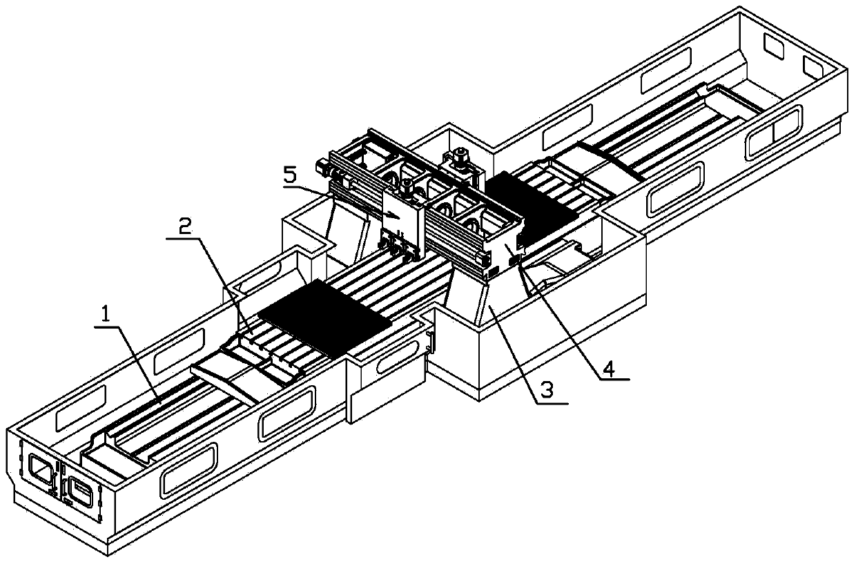
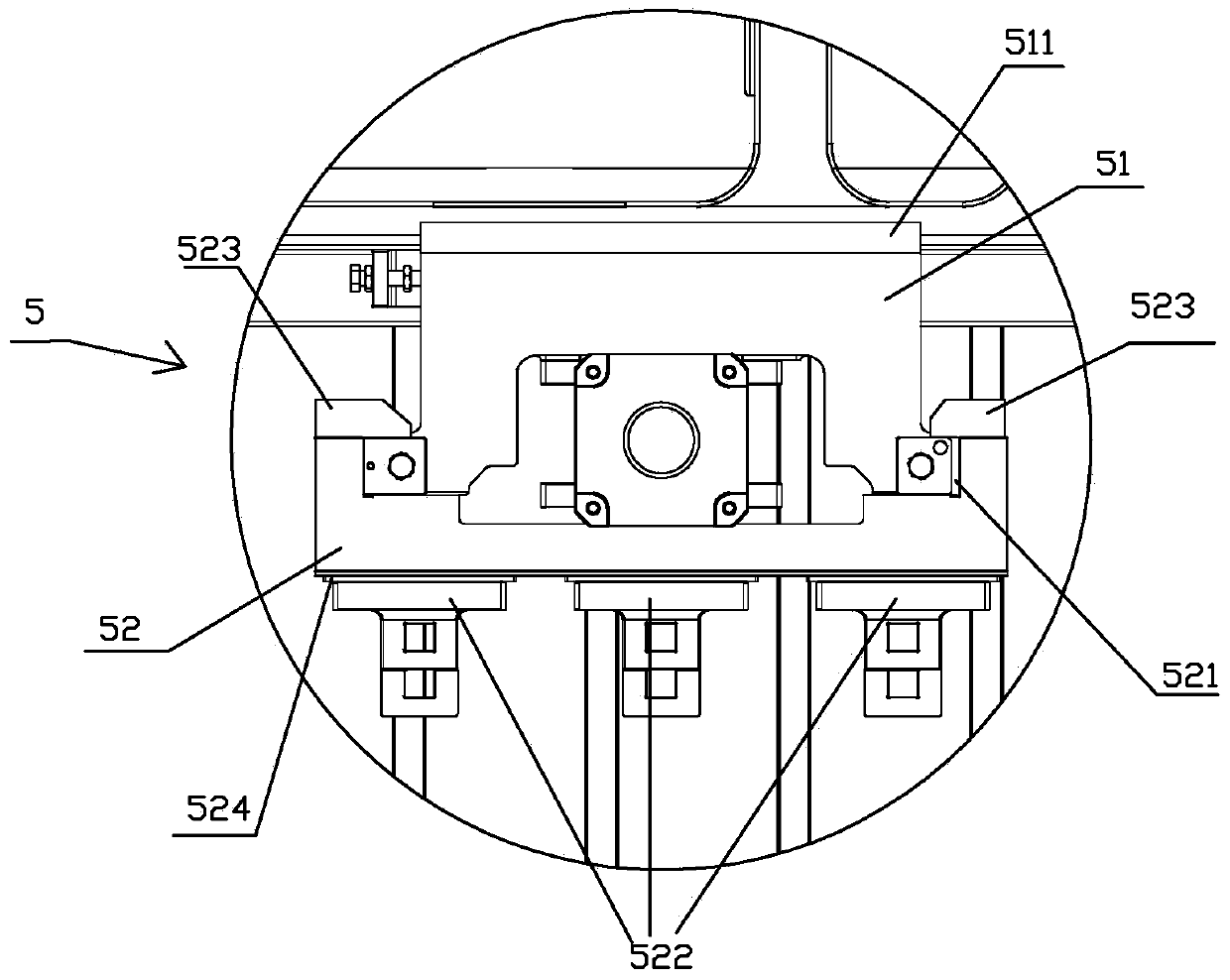
[0020] Embodiment: a kind of planing mechanism that is used for numerical control planer, as image 3 , 4 , 5, the slicing mechanism 5 includes a horizontal feed slide 51 and a lifting carriage 52, the horizontal feed slide 51 is provided with a screw B, and the screw B is threadedly connected with a screw nut. The rod nut is fixedly installed on the horizontal feed slide 51 through the nut seat; the screw C and the motor C are installed on the horizontal feed slide 51, and the lifting carriage 52 is installed on the horizontal feed slide 51 and can be moved horizontally. Slide up and down vertically for slide seat 51, and described vertical direction refers to figure 1 In the direction perpendicular to the longitudinal and transverse directions at the same time, the screw C is vertically installed on the horizontal feed slide 51 through the bearing and the bearing seat, the screw C is threadedly connected with the screw nut C, and the screw nut C is set through the nut seat ...


PUM


Abstract

The invention relates to a numerically controlled planer, in particular to a slicing mechanism for the numerically controlled planer. The slicing mechanism comprises a horizontal feeding side rest and a lifting carriage. Vertical motion of a transverse beam of an existing planer is replaced by vertical motion of the lifting carriage, and since the lifting carriage is lighter than the transverse beam, carrying load of a machine is lowered, and service life of the machine is prolonged. By the aid of the slicing mechanism, the problem of short service life of the existing planer is solved.

Description

technical field [0001] The invention relates to a numerical control planer, in particular to a cutting mechanism for a numerical control planer. Background technique [0002] Gantry planer is a common equipment in the processing field. When the existing gantry planer processes parts, the beam needs to reciprocate up and down along the column. Because the weight of the beam is relatively large, it is easy to damage the rotating equipment during the up and down reciprocating movement. Moreover, the existing gantry planer The processing equipment is only set on one side of the beam, so multiple workpieces cannot be processed at the same time, and the efficiency is low; and the stability of the existing planer is poor, and the stability of the operation of the planer cannot be guaranteed, thereby affecting the machining accuracy. [0003] Therefore, the present inventor has designed a kind of numerical control gantry planer, and this numerical control gantry planer has the advan...

Claims


Application Information

Patent Timeline
Patent Type & Authority Applications(China)
IPC IPC(8): B23D7/10B23D7/00
Inventor 沈平高尔荣
Owner 徐州领君自动化设备有限公司
Why Eureka
Try Eureka