Natural gas hydrate core under-pressure transfer method and apparatus

A transfer method and transfer device technology, which are used in the preparation of test samples, etc.

Inactive Publication Date: 2014-07-09
CHINA PETROLEUM & CHEM CORP +1
View PDF2 Cites 19 Cited by
  • Summary
  • Abstract
  • Description
  • Claims
  • Application Information

AI Technical Summary

Problems solved by technology

Although natural gas hydrate can be obtained in this way, some physical and chemical properties of natural gas hydrate will inevitably be affected after freezing, so even if the gas hydrate is tested after thawing, it cannot be guaranteed that the obtained in-situ characteristics of natural gas hydrate

Method used


Image

  • Natural gas hydrate core under-pressure transfer method and apparatus

Examples


Embodiment 1

[0020] Embodiment 1 is a kind of optimized typical embodiment

[0021] First, a gas hydrate core transfer method under pressure.

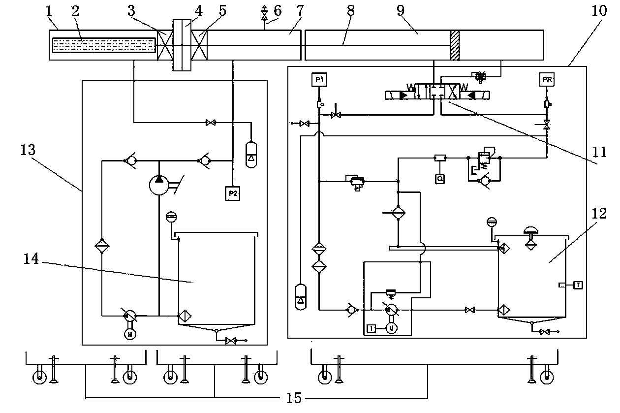
[0022] The first step is to establish an end-to-end connection between the pressure-holding cylinder with the core tube and another transfer chamber with the same specifications as the pressure-holding cylinder; the second step is to send the core tube in the pressure-holding cylinder into the transfer chamber; The third step is to close the transfer bin and disconnect the connection with the pressure holding cylinder; in the above three steps, it is necessary to use an external pressure balance control system to always keep the pressure of the transfer bin the same as the initial state pressure of the pressure holding cylinder.

[0023] Wherein, the method for sending the core tube in the pressure-holding cylinder into the transfer bin is to use an external pull rod to pull the core tube in the pressure-holding tube into the transfer bin.

[0024...

Embodiment 2

[0028] Embodiment 2 is a simplified typical embodiment

[0029] First, a gas hydrate core transfer method under pressure.

[0030] The first step is to establish an end-to-end connection between the pressure-holding cylinder with the core tube and another transfer chamber with the same specifications as the pressure-holding cylinder; the second step is to send the core tube in the pressure-holding cylinder into the transfer chamber; The third step is to close the transfer bin and disconnect the connection with the pressure holding cylinder; in the above three steps, it is necessary to use an external pressure balance control system to always keep the pressure of the transfer bin the same as the initial state pressure of the pressure holding cylinder.

[0031] In the above-mentioned gas hydrate core transfer method under pressure, the method of sending the core tube in the pressure-holding cylinder into the transfer chamber is as follows: the docked pressure-holding cylinder an...


PUM


Abstract

The present invention relates to a natural gas hydrate core under-pressure transfer method, which comprises: establishing end-to-end connection between a pressure keeping cylinder filled with a core tube and a transfer bin having the specification equivalent to the pressure keeping cylinder, conveying the core tube in the pressure keeping cylinder into the transfer bin, sealing the transfer bin, and disconnecting the connection of the pressure keeping cylinder, wherein the pressure of the transfer bin and the initial state pressure of the pressure keeping cylinder are always maintained the same during the steps. The invention further relates to an apparatus applying the method, wherein the opposite connection ends of the pressure keeping cylinder and the transfer bin are respectively connected with a pressure keeping cylinder valve and a transfer bin valve, the valves are sealed and communicated through a flange, and the internals of the pressure keeping cylinder and the transfer bin respectively establish a connection with a pressure balancing control system. According to the present invention, the natural gas hydrate is in the under-pressure state, such that it is ensured that gas, pore water and other components in the core are not changed, and the detected data after the core treatment is close to the in situ situation so as to provide basis for analysis of natural gas hydrate characteristics and determination of reserves.

Description

technical field [0001] The invention relates to the technical field of new energy exploration and development sampling and transfer, in particular to a method and device for transferring natural gas hydrate cores under pressure. Background technique [0002] Since gas hydrates decompose rapidly under normal pressure, to obtain in-situ gas hydrate samples, pressure-holding coring is required. To transfer the pressurized core to the core post-processing studio, a pressurized transfer device is required. It must be able to ensure that the gas hydrate core is transferred to a pressured and easily movable transfer chamber without decomposing. Then the transfer chamber can be sent to the core post-processing studio through conventional transportation to realize the in-situ test of gas hydrate. [0003] At present, the transfer of natural gas hydrate samples mainly depends on freezing, that is, after the pressure-holding core is obtained, the pressure is released quickly and put ...

Claims


Application Information

Patent Timeline
Patent Type & Authority Applications(China)
IPC IPC(8): G01N1/28
Inventor 任红许俊良吴仲华马清明韩来聚朱杰然
Owner CHINA PETROLEUM & CHEM CORP
Why Eureka
Try Eureka