Separating apparatus

A technology for separating equipment and substrates, applied in the direction of layered products, lamination auxiliary operations, electronic equipment, etc., can solve problems such as inconvenience, difficult rework, and easy breakage

Active Publication Date: 2014-07-16
E INK HLDG INC
View PDF5 Cites 10 Cited by
  • Summary
  • Abstract
  • Description
  • Claims
  • Application Information

AI Technical Summary

Problems solved by technology

Furthermore, when the thin wire passes through the wire cutting and sealing, it is easier to have residual glue on the display panel or touch panel
In addition, because of the low strength of thin wire, it is easier to break when a large force is used, resulting in an increase in cost
Therefore, the existing conventional separation equipment is used to separate the components of the electronic device, which is quite inconvenient to use, not only time-consuming and labor-intensive, but also difficult to rework.
[0004] This shows that the above-mentioned existing separation equipment obviously still has inconvenience and defects in structure and use, and needs to be further improved urgently.

Method used


Image

  • Separating apparatus
  • Separating apparatus
  • Separating apparatus

Examples


Embodiment Construction

[0030] In order to further explain the technical means and effects of the present invention to achieve the intended purpose of the invention, the specific implementation, structure, characteristics and effects of the separation equipment proposed according to the present invention will be described in detail below in conjunction with the accompanying drawings and preferred embodiments. The description is as follows.

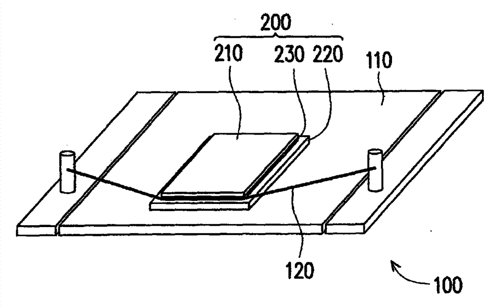
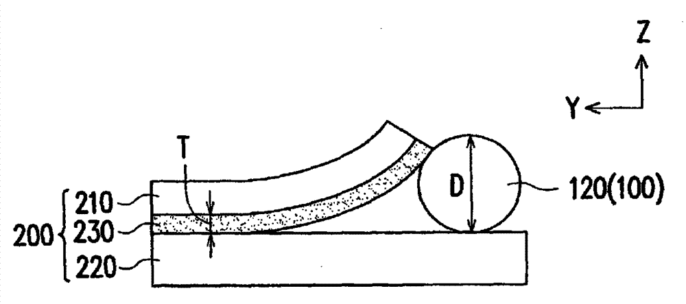
[0031] figure 1 It is a schematic diagram of a separation device and an electronic device according to an embodiment of the present invention. figure 2 shown as figure 1 A partially enlarged cross-sectional schematic diagram of the wire and electronic device of the separation device. Please also refer to figure 1 and figure 2 , in this embodiment, the separation device 100 includes a base 110 and a wire 120 . The base 110 is suitable for carrying the electronic device 200 . The electronic device 200 includes a first substrate 210 , a second substrate 220 ...


PUM

PropertyMeasurementUnit
thicknessaaaaaaaaaa

Abstract

A separating apparatus, including a base and a wire, is provided. The base is adapted for carrying an electronic device. The electronic device includes a first substrate, a second substrate, and an adhesive layer. The adhesive layer adheres the first substrate and the second substrate to each other. The wire is configured on the base. A wire diameter of the wire is equal to or greater than a thickness of the adhesive layer.

Description

technical field [0001] The present invention relates to a separation device, and in particular to a separation device for separating two substrates pasted together. Background technique [0002] With the progress of the information industry, electronic products with multiple functions such as display function, touch function and stereoscopic display function are popular because of their higher convenience. At present, most of these multi-functional electronic products are achieved by plug-in. For example, when the electronic device is required to have display function and touch function at the same time, the touch panel and the display panel can be pasted together by sealing glue to form the required electronic device. Of course, in order to increase the display quality, a front-light module (front-light module) can also be added in front of a display panel with a display function, such as an electrophoretic display (Electro Phonetic Display, EPD) panel or a liquid crystal ...

Claims


Application Information

Patent Timeline
Patent Type & Authority Applications(China)
IPC IPC(8): B32B38/10
CPCB32B2457/20B32B43/006Y10T156/1911
Inventor 李宗庭游钦祺
Owner E INK HLDG INC
Why Eureka
Try Eureka