Working condition monitoring and fault diagnosis method for mechanical equipment

A technology for mechanical equipment and fault diagnosis, applied in the direction of testing, measuring devices, instruments, etc. of machine/structural components, which can solve the problem of rarely considering the interconnection, the useful information of time domain parameters is not fully excavated and utilized, and it is difficult to mechanically Reasonable prediction of equipment operating conditions and other issues to achieve low-cost results

Active Publication Date: 2014-08-06
常州晶容创机械科技有限公司
View PDF5 Cites 20 Cited by
  • Summary
  • Abstract
  • Description
  • Claims
  • Application Information

AI Technical Summary

Problems solved by technology

In many previous literatures, people pay more attention to the change of single time-domain parameters over time, and seldom consider the interrelationships between these factors, as well as the relationship between these connections and mechanical equipment failures, so that the useful information inside the time-domain parameters If it is not fully excavated and utilized, it is difficult to achieve a reasonable prediction of the working conditions of mechanical equipment

Method used


Image

  • Working condition monitoring and fault diagnosis method for mechanical equipment
  • Working condition monitoring and fault diagnosis method for mechanical equipment
  • Working condition monitoring and fault diagnosis method for mechanical equipment

Examples


Embodiment Construction

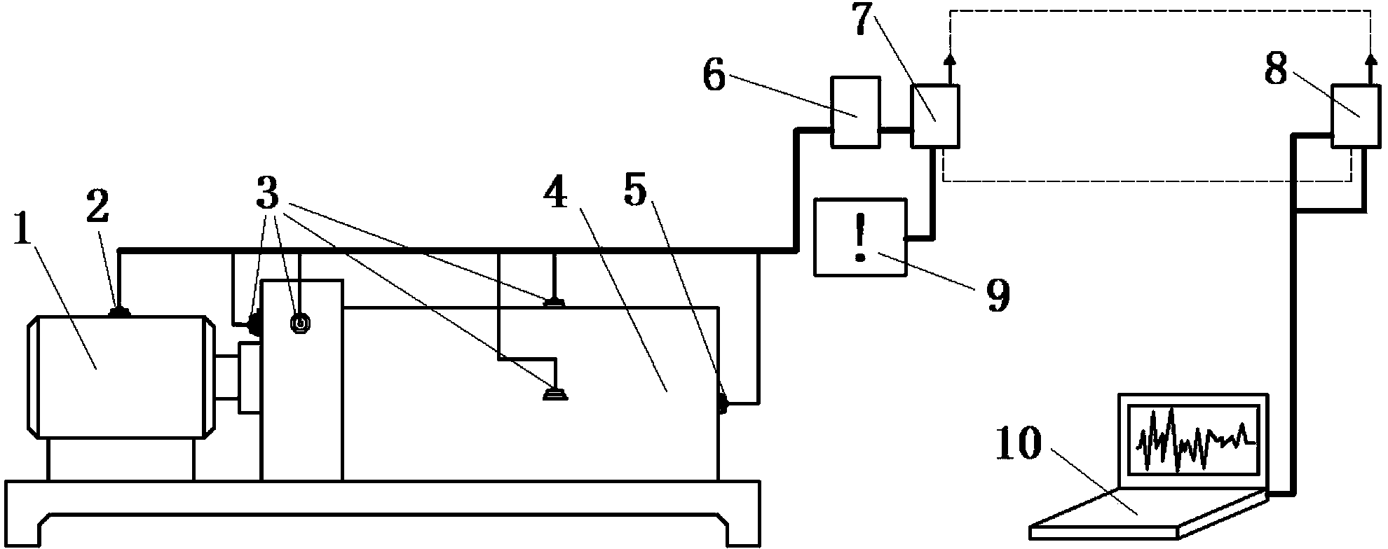
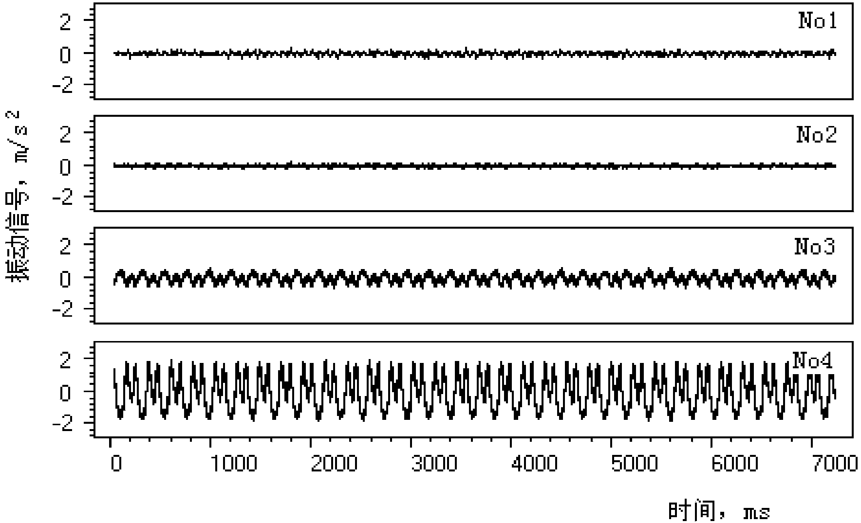
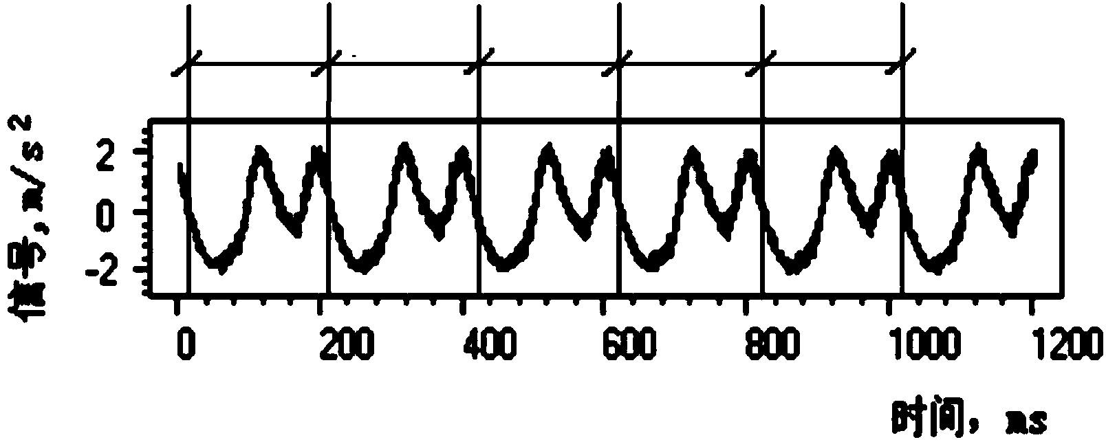
[0034] Referring now to the schematic diagram, combined with a test example of a gear transmission system, the implementation of this monitoring method and the application of this signal processing technology will be described.

[0035] 1) Composition of the device

[0036] like figure 1 As shown, the mechanical equipment in this embodiment is the GLS-II gear efficiency test system produced by Hangzhou Xingchen Science and Education Equipment Co., Ltd., and the vibration signal of the equipment is collected by the UBOX-20016 blasting vibration recorder.

[0037] The speed of the gear efficiency test system can be flexibly adjusted through the "rotational speed adjustment knob", and the output torque of the system is adjusted by the number of weights placed on the force arm, which can be changed between 0-8 weights, each The weight of the weight is 1 kg. The number of weights on the hook multiplied by the length of the cantilever is the output torque of the transmission syste...


PUM


Abstract

The invention relates to a working condition monitoring and fault diagnosis method for mechanical equipment. The method includes the steps that (1), vibration signals are collected; (2), primitive segmentation is performed on the signals; (3), the signals are separated and classified; (4), parameter statistics is performed on the separated signals; (5), two-parameter distribution displaying is performed, wherein all kinds of separated signals are displayed on a two-parameter plane in a scatter plot mode; (6), a motion state matrix is established; (7), by the utilization of the motion state matrix established in the step6, actual measurement vibration signal statistics and equipment state qualitative recognition are performed; (8), a quantitative relation model among the working state, working parameters and separation signal time domain statistics results is established; (9), in the real-time monitoring process, the separation signal time domain parameter statistics results are substituted into the quantitative relation model established in the step8, so that quantitative predication and fault quantitative diagnosis performed on the working parameters are achieved. Through a simple signal monitoring device low in cost, data are collected, and the working conditions of the mechanical equipment are monitored and recognized in real time. By the adoption of the simple algorithm, qualitative diagnosis performed on faults and quantitative predication performed on the working condition parameters are achieved, so that conditions are created for state monitoring and scientific fault quantitative diagnosis of the mechanical equipment.

Description

technical field [0001] The invention discloses a method for monitoring and fault diagnosis of mechanical equipment working conditions, which uses vibration signals and acoustic signals generated by mechanical equipment during operation to monitor the working state of mechanical equipment, evaluate working parameters, and diagnose various faults, belonging to engineering machinery equipment field. Background technique [0002] In the field of construction machinery, equipment failures are often encountered, resulting in serious economic losses and even casualties. The purpose of mechanical fault diagnosis is to timely and correctly diagnose various abnormal states or mechanical faults, prevent or eliminate faults, provide necessary guidance to the operation of equipment, and improve the reliability, safety and effectiveness of equipment operation. To reduce faults to the lowest level, to ensure the best performance of equipment, and to provide data and information for equipm...

Claims


Application Information

Patent Timeline
Patent Type & Authority Applications(China)
IPC IPC(8): G01M99/00
Inventor 吕苗荣徐清武金瑞梁鹏宇
Owner 常州晶容创机械科技有限公司
Why Eureka
Try Eureka