Switchgear and its control method

A lighting switch and selector switch technology, which is applied in energy-saving control technology, lighting and heating equipment, lighting devices, etc., can solve the problem that the lighting switch cannot well meet the diversified control needs of users, the safety and reliability of the lighting switch are low, It is easy to cause problems such as operation interference, so as to achieve the effect of convenient and fast switching operation, avoiding control interference and reducing interference.

Active Publication Date: 2016-03-02
ZHUHAI UNITECH POWER TECH CO LTD
View PDF6 Cites 0 Cited by
  • Summary
  • Abstract
  • Description
  • Claims
  • Application Information

AI Technical Summary

Problems solved by technology

If the user needs to stay in the space for a long time, the lighting equipment needs to be continuously illuminated, and the user can only frequently activate the voice-activated switch or the temperature-controlled switch to supply power, which is very cumbersome and inconvenient to operate
The lighting switches of most existing lighting systems generally have a single working mode. Once the control mode fails or does not meet the user's specific control requirements, the lighting switch cannot well meet the user's diversified control needs.
In addition, some lighting switches have manual control mode and automatic control mode, the control structure is complicated, and operation interference between different control modes is easy to occur, and the safety and reliability of such lighting switches are low

Method used


Image

  • Switchgear and its control method
  • Switchgear and its control method
  • Switchgear and its control method

Examples


Embodiment Construction

[0041] The specific embodiments of the present invention will be described in detail below in conjunction with the accompanying drawings of the specification, but the present invention can be implemented in many different ways defined and covered by the claims.

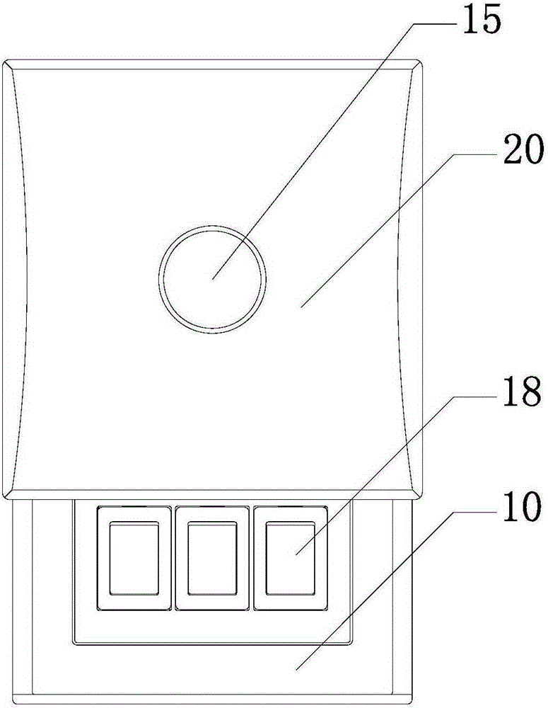
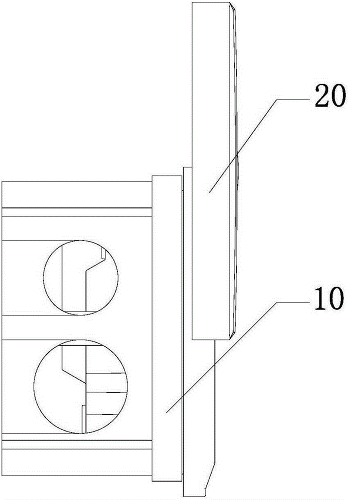
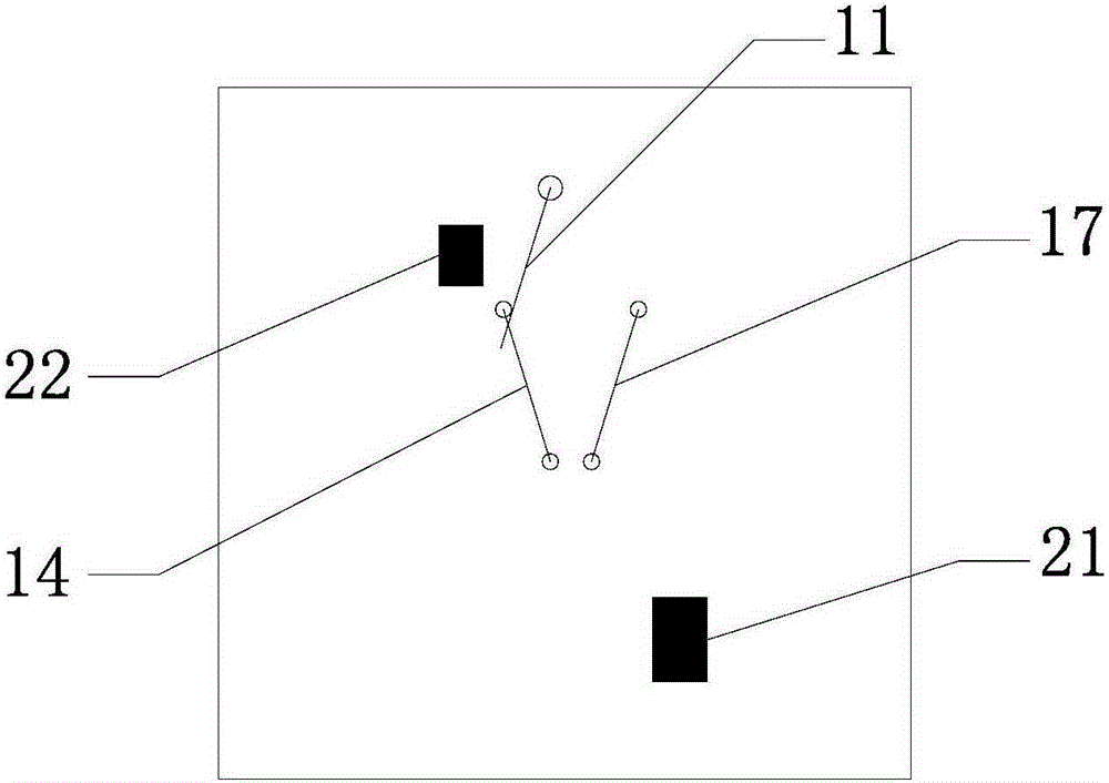
[0042] On the one hand, such as Figure 1 to Figure 11 As shown, the lighting switch of the present invention includes a bottom box 10 and a box cover 20. The box cover 20 is opened and closed on the bottom box 10. The bottom box 10 is provided with a selector switch 11, an automatic control circuit 13 and a manual control circuit. 16. Among them, the selector switch 11 can be a single-pole double-throw switch, the automatic control circuit 13 and the manual control circuit 16 are each connected to the fixed end of a single-pole double-throw switch, the selector switch 11 can also be a conversion relay, and the automatic control circuit 13 and The manual control loop 16 is each connected to a static contact of a conversio...


PUM


Abstract

The invention discloses a switchgear and a control method of the switchgear. A box cover of the switchgear is arranged on a bottom box in an openable mode, an option switch, an automatic control loop and a manual control loop are arranged in the bottom cover, an automatic switch is arranged on the automatic control loop, a manual switch is arranged on the manual control loop, and the option switch is in synchronous linkage with the box cover. When the box cover is opened, the manual switch is exposed, the manual control loop is closed through the option switch, and the automatic control loop is opened; when the box cover is closed, the manual switch is hidden, the automatic control loop is closed through the option switch, and the manual control loop is opened. According to the switchgear and the control method of the switchgear, free switching between a manual control mode and an automatic control mode is achieved through opening and closing of the box cover and linkage between different control loops, the control structure is simple, and switching is convenient to operate; the two modes are independent from each other, when one mode is in work, the other mode is forbidden, control interference caused by misoperation is avoided, and therefore safety and reliability are ensured.

Description

Technical field [0001] The invention relates to the field of switch control, in particular to a lighting switch and a control method thereof. Background technique [0002] Currently, traditional lighting switches mostly use mechanical manual switches, such as rocker switches, which are manually pressed to turn on or off the lighting equipment. With the continuous updating of automation technology and information technology, these new technologies have gradually entered the field of smart homes, and smart lighting systems have also emerged. The automatic switch used in the intelligent lighting system enables the control of the lighting switch to be automatically realized through the combination of a controller and a relay, and is widely used, such as road lighting systems, hotel room lighting, etc. [0003] In view of the improvement of living standards, people's needs are also diversified. In terms of lighting equipment control, for various reasons, users may sometimes want to re...

Claims


Application Information

Patent Timeline
Patent Type & Authority Patents(China)
IPC IPC(8): H05B37/02F21V23/04
CPCY02B20/40
Inventor 金述强张永强江海峰吴志洪
Owner ZHUHAI UNITECH POWER TECH CO LTD
Why Eureka
Try Eureka