Mini-type pressure reduction pipe

A decompression tube and miniature technology, which is applied to functional valve types, safety valves, engine components, etc., can solve the problems of unstable flame state, flow fluctuation, and inability to install, so as to avoid unstable flame state and stable gas output flow. , the effect of improving assembly efficiency

Inactive Publication Date: 2014-11-05
CHENGDU GUOGUANG ELECTRONICS INSTR
View PDF7 Cites 2 Cited by
  • Summary
  • Abstract
  • Description
  • Claims
  • Application Information

AI Technical Summary

Problems solved by technology

The existing pressure reducing valve has complex structure, high manufacturing cost, and the pressure reducing valve is too large to be installed in a narrow space
[0003] Existing decompression valves, such as a high-pressure natural gas decompression valve disclosed in Chinese Patent Application Publication No. "102052495A", natural gas flows in from the intake end, and enters from the top and bottom direction after passing through the decompression mechanism. When the gas outlet is connected to the cavity, the natural gas will be sprayed onto the cavity wall at this time, causing the natural gas flow entering the gas outlet to be turbulent, which can easily cause flow fluctuations and cause the flame state to be unstable when the user uses it.
[0004] At the same time, the existing pressure reducing valve uses a spring as a force-receiving mechanism, and the length of the spring is relatively long, resulting in a large volume of the existing pressure reducing valve, while using a spring with a small size cannot provide sufficient elastic force, resulting in insufficient gas pressure. The extent to which the decayed value is available

Method used


Image

  • Mini-type pressure reduction pipe
  • Mini-type pressure reduction pipe
  • Mini-type pressure reduction pipe

Examples


Embodiment 1

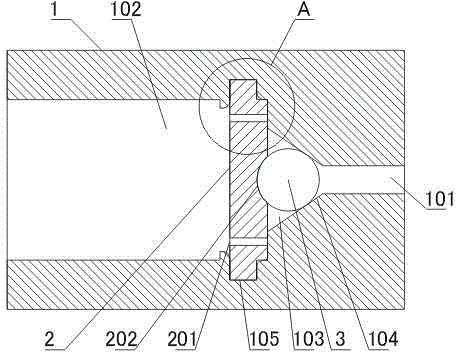
[0039] like figure 1 As shown, the miniature decompression tube includes a pipe body 1, and connecting threads are provided at both ends of the pipe body 1. The space in the pipe body 1 is composed of a high-pressure chamber 101 and a low-pressure chamber 102; the inner diameter of the high-pressure chamber 101 is smaller than the inner diameter of the low-pressure chamber 102 The rubber sheet 2, the rubber sheet 2 is arranged in the low-pressure chamber 102 and is connected with the inner surface of the low-pressure chamber 102, the rubber sheet 2 is in contact with the end of the high-pressure chamber 101, and the rubber sheet 2 and the end of the high-pressure chamber 101 are evenly opened There are a plurality of air outlet holes 201, and an arc groove 202 is opened at the center of the rubber sheet 2; the accommodation cavity 103 is set at one end of the high-pressure chamber 101 close to the rubber sheet 2, and the sealing ball 3 is placed in the arc groove In 202 , the ...

Embodiment 2

[0046] like figure 1 As shown, this embodiment is based on Embodiment 1, and the transition is a tapered surface 104 .

[0047]The sealing ball 3 cooperates with the tapered surface 104 to improve the sealing performance and further prevent the gas in the high-pressure chamber 101 from entering the low-pressure chamber 102 when the user does not use the gas, causing the gas pressure to be too high when the user starts to use the gas.

Embodiment 3

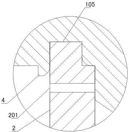
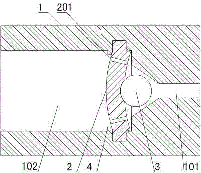
[0049] like figure 1 and image 3 As shown, this embodiment is based on Embodiment 1 or 2, the inner surface of the low-pressure chamber 102 is provided with an annular groove 105 , and the edge of the rubber sheet 2 is located in the annular groove 105 .

[0050] The circular groove 105 is provided, and the rubber sheet 2 can be conveniently installed in the circular groove 105, which improves the assembly efficiency of the present invention.


PUM


Abstract

The invention discloses a mini-type pressure reduction pipe. The mini-type pressure reduction pipe comprises a pipe body, a rubber sheet, a containing cavity and a ball sealer, wherein the two ends of the pipe body are provided with connection threads, the space inside the pipe body is composed of a high pressure cavity and a low pressure cavity, the inner diameter of the high pressure cavity is smaller than that of the low pressure cavity, the rubber sheet is arranged inside the low pressure cavity and is connected with the inner surface of the low pressure cavity, the rubber sheet makes contact with the end portion of the high pressure cavity, the position where the rubber sheet makes contact with the end portion of the high pressure cavity is evenly provided with multiple vent holes, a circular arc groove is formed in the center of the rubber sheet, the containing cavity is arranged at one end, close to the rubber sheet, of the high pressure cavity, the ball sealer is arranged inside the circular arc groove, and the ball sealer is compressed in the containing cavity by the rubber sheet and is tightly attached to the transition position of the containing cavity. The rubber sheet replaces a spring, so that the size of the pressure reduction pipe is reduced effectively.

Description

technical field [0001] The invention relates to the field of gas delivery, in particular to a gas delivery device. Background technique [0002] The gas needs to be kept at high pressure during the transportation process, and the gas pressure needs to be reduced when it is used at the user end. Currently, in order to reduce the gas pressure at the user end, a pressure reducing valve is usually provided on the gas delivery pipe. The existing pressure reducing valve has complicated structure and high manufacturing cost, and the pressure reducing valve has a large volume and cannot be installed in a narrow space. [0003] Existing decompression valves, such as a high-pressure natural gas decompression valve disclosed in Chinese Patent Application Publication No. "102052495A", natural gas flows in from the intake end, and enters from the top and bottom direction after passing through the decompression mechanism. When the gas outlet is connected to the cavity, the natural gas w...

Claims


Application Information

Patent Timeline
Patent Type & Authority Applications(China)
IPC IPC(8): F16K17/24
CPCF16K17/0406
Inventor 吕忠贵
Owner CHENGDU GUOGUANG ELECTRONICS INSTR
Why Eureka
Try Eureka