Al technical title is built by PatSnap Al team. It summarizes the technical point description of the patent document.
A technology for replacing machines and sleepers, which is applied to tracks, track laying, track maintenance, etc., and can solve problems such as time-consuming and laborious work efficiency, sleeper sinking, and sleeper damage.
Inactive Publication Date: 2015-11-18
KUNMING UNIV
View PDF5 Cites 0 Cited by
Summary
Abstract
Description
Claims
Application Information
AI Technical Summary
This helps you quickly interpret patents by identifying the three key elements:
Problems solved by technology
Method used
Benefits of technology
Problems solved by technology
[0002] During the long-term use of railway sleepers, due to natural settlement and vibration, some railway sleepers sink and need maintenance. Individual sleepers are damaged and need to be replaced in time. In the process of sleeper replacement, manual work is used, which is time-consuming and laborious. The work efficiency is low, and the work of changing the pillow cannot be completed within the effective train passage gap (commonly known as: skylight)
Method used
Image
Click on the blue label to locate the original text in one second.
Reading with bidirectional positioning of images and text.
Examples
Embodiment Construction
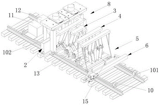
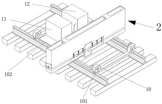
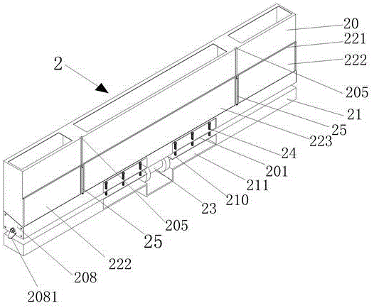
[0119] see figure 1 , figure 2 , Figure 11 , Figure 18 , Figure 23 , Figure 32 , Figure 45 Shown, be the embodiment of the present invention, and this embodiment is by being the embodiment of the present invention, and this embodiment is by ballast collecting device 2, vibrating rock pushing device 3, four nuts synchronous assembly and disassembly device 4, lifting rail turning Sleeper device 5, sleeper push-pull device 6, lateral movement vibration rotary excavation rock removal device 8, rail car 10, generator 11, hydraulic system box 12, first camera assembly 13, second camera assembly 14, third camera assembly 15, The fourth camera assembly 16 is composed of a monitor. The rail car 10 is equipped with a plurality of casters 101 and two longitudinal beams 102, a ballast collecting and discharging device 2, a vibrating stone pushing device 3, a four-nut synchronous assembly and disassembly device 4, a rail lifting and turning sleeper device 5, a sleeper pushing a...
PUM
Abstract
The invention discloses a mechanization sleeper replacement device. The mechanization sleeper replacement device is composed of a ballast collection and discharging device, a vibration stone pushing device, a four nut synchronization assembly and disassembly device, a rail lifting sleeper rotation device, a sleeper pushing and pulling device, a transverse moving vibration rotary excavating stone discharging device, a rail car, an electric generator, a hydraulic system case, a first camera component, a second camera component, a third camera component, a forth camera component and a monitor, wherein a plurality of trundles and two longitudinal beams are installed on the rail car, the ballast collection and discharging device, the vibration stone pushing device, the four nut synchronization assembly and disassembly device, the rail lifting sleeper rotation device, the sleeper pushing and pulling device, the transverse moving vibration rotary excavating stone discharging device, the electric generator and the hydraulic system case are arrange on the two longitudinal beams of the rail car, and the monitor is arranged in a cab of a tractor truck. The mechanization sleeper replacement device can rapidly align a working device to a position to be processed, can adapt to sleeper replacement work at straight and curve rail segments, easily achieves program automatic control, is convenient to operate, and can fully and reasonably use limited line repair skylight operation time to complete the sleeper replacement work.
Description
technical field [0001] The invention relates to a railway maintenance machine, in particular to a mechanized sleeper replacement machine. Background technique [0002] During the long-term use of railway sleepers, due to natural settlement and vibration, some railway sleepers sink and need maintenance. Individual sleepers are damaged and need to be replaced in time. In the process of sleeper replacement, manual work is used, which is time-consuming and laborious. The work efficiency is low, and the work of changing the pillow cannot be completed in the effective train passage gap (commonly known as: skylight). Contents of the invention [0003] The object of the present invention is to provide a mechanized sleeper replacement machine. [0004] The present invention is composed of a ballast collecting and discharging device, a vibrating stone pushing device, a four-nut synchronous assembly and dismounting device, a rail lifting and turning sleeper device, a push-pull sleep...
Claims
Application Information
Patent Timeline
Application Date:The date an application was filed.
Publication Date:The date a patent or application was officially published.
First Publication Date:The earliest publication date of a patent with the same application number.
Issue Date:Publication date of the patent grant document.
PCT Entry Date:The Entry date of PCT National Phase.
Estimated Expiry Date:The statutory expiry date of a patent right according to the Patent Law, and it is the longest term of protection that the patent right can achieve without the termination of the patent right due to other reasons(Term extension factor has been taken into account ).
Invalid Date:Actual expiry date is based on effective date or publication date of legal transaction data of invalid patent.